

珀金斯Perkins1104C-E44(T)(TA)操作保養(yǎng)(英文)
詳細(xì)描述
Operation and
Maintenance
Manual
1104E Engine
RF (Engine)
R H ( Engine)
R K ( Engine)
This document has been printed from SPI². Not for Resale
![]()
![]()
![]()
![]()
![]()
i01658146
ImportantSafetyInformation
Mostaccidentsthatinvolveproductoperation,maintenanceandrepairarecausedbyfailuretoobserve
basicsafetyrulesorprecautions.Anaccidentcanoftenbeavoidedbyrecognizingpotentiallyhazardous
situationsbeforeanaccidentoccurs.Apersonmustbealerttopotentialhazards.Thispersonshouldalso
havethenecessarytraining,skillsandtoolstoperformthesefunctionsproperly.
Improperoperation,lubrication,maintenanceorrepairofthisproductcanbedangerousand
couldresultininjuryordeath.
Donotoperateorperformanylubrication,maintenanceorrepaironthisproduct,untilyouhave
readandunderstoodtheoperation,lubrication,maintenanceandrepairinformation.
Safetyprecautionsandwarningsareprovidedinthismanualandontheproduct.Ifthesehazardwarnings
arenotheeded,bodilyinjuryordeathcouldoccurtoyouortootherpersons.
Thehazardsareidentifiedbythe“SafetyAlertSymbol”andfollowedbya“SignalWord”suchas
“DANGER”,“WARNING”or“CAUTION”.TheSafetyAlert“WARNING”labelisshownbelow.
Themeaningofthissafetyalertsymbolisasfollows:
Attention!BecomeAlert!YourSafetyisInvolved.
Themessagethatappearsunderthewarningexplainsthehazardandcanbeeitherwrittenorpictorially
presented.
Operationsthatmaycauseproductdamageareidentifiedby“NOTICE”labelsontheproductandin
thispublication.
Perkins cannot anticipa te e ver y p os sible c irc u mstance t hat m ight invol ve a pote n ti al hazard .
Thewarningsinthispublicationandontheproductare,therefore,notallinclusive.Ifatool,
proc edure, work me thod or ope rating technique tha t is not s pecific ally rec ommended by Perkins
isused,youmustsatisfyyourselfthatitissafeforyouandforothers.Youshouldalsoensurethat
theproductwillnotbedamagedorbemadeunsafebytheoperation,lubrication,maintenanceor
repairproceduresthatyouchoose.
Theinformation,specifications,andillustrationsinthispublicationareonthebasisofinformationthat
wasavailableatthetimethatthepublicationwaswritten.Thespecifications,torques,pressures,
measurements,adjustments,illustrations,andotheritemscanchangeatanytime.Thesechangescan
affecttheservicethatisgiventotheproduct.Obtainthecompleteandmostcurrentinformationbeforeyou
s t ar t any jo b . Perkins dea le rs hav e t he m os t c ur r en t i nfo rm ati on a va il abl e.
When replacement parts are required for this
product Perkinsre comme nds usi ng Perkins
re pl ace ment parts or parts w ith equiva lent
specificationsincluding,butnotlimitedto, phys-
icaldimensions,type,strengthandmaterial.
Failuretoheedthiswarningcanleadtoprema-
turefailures,productdamage,personalinjuryor
death.
This document has been printed from SPI². Not for Resale
![]()
![]()
![]()
SEBU8121
3
Table of Contents
Table of Contents
Warranty Section
Warranty Information ............................................ 81
Foreword ................................................................. 4
Index Section
Safety Section
Index ..................................................................... 82
Safety Messages .................................................... 5
General Hazard Information ................................... 5
Burn Prevention ...................................................... 7
Fire Prevention and Explosion Prevention .............. 7
Crushing Prevention and Cutting Prevention .......... 9
Before Starting Engine ............................................ 9
Engine Starting ....................................................... 9
Engine Stopping ................................................... 10
Electrical System .................................................. 10
Engine Electronics ................................................. 11
Product Information Section
General Information .............................................. 12
Model Views ......................................................... 13
Product Identification Information ........................ 17
Operation Section
Lifting and Storage ................................................ 19
Gauges and Indicators .......................................... 22
Features and Controls .......................................... 23
Engine Diagnostics ............................................... 27
Engine Starting ..................................................... 29
Engine Operation .................................................. 33
Engine Stopping ................................................... 34
Cold Weather Operation ....................................... 35
Maintenance Section
Refill Capacities .................................................... 39
Maintenance Interval Schedule ............................ 52
This document has been printed from SPI². Not for Resale
![]()
![]()
4
SEBU8121
Foreword
Foreword
Recommended service should be performed at the
appropriate intervals as indicated in the Maintenance
Interval Schedule. The actual operating environment
of the engine also governs the Maintenance Interval
Schedule. Therefore, under extremely severe,
dusty, wet or freezing cold operating conditions,
more frequent lubrication and maintenance than is
specified in the Maintenance Interval Schedule may
be necessary.
Literature Information
This manual contains safety, operation instructions,
lubrication and maintenance information. This
manual should be stored in or near the engine area
in a literature holder or literature storage area. Read,
study and keep it with the literature and engine
information.
The maintenance schedule items are organized for
a preventive maintenance management program. If
the preventive maintenance program is followed, a
periodic tune-up is not required. The implementation
of a preventive maintenance management program
should minimize operating costs through cost
avoidances resulting from reductions in unscheduled
downtime and failures.
English is the primary language for all Perkins
publications. The English used facilitates translation
and consistency.
Some photographs or illustrations in this manual
show details or attachments that may be different
from your engine. Guards and covers may have
been removed for illustrative purposes. Continuing
improvement and advancement of product design
may have caused changes to your engine which are
not included in this manual. Whenever a question
arises regarding your engine, or this manual, please
consult with your Perkins dealer or your Perkins
distributor for the latest available information.
Maintenance Intervals
Perform maintenance on items at multiples of
the original requirement. We recommend that the
maintenan
ce schedules be reproduced and displayed
near the engine as a convenient reminder. We also
recommend that a maintenance record be maintained
as part of the engine’s permanent record.
Safety
Your authorized Perkins dealer or your Perkins
distributor can assist you in adjusting your
maintenance schedule to meet the needs of your
operating environment.
This safety section lists basic safety precautions.
In addition, this section identifies hazardous,
warning situations. Read and understand the basic
precautions listed in the safety section before
operating or performing lubrication, maintenance and
repair on this product.
Overhaul
Major engine overhaul details are not covered in
the Operation and Maintenance Manual except
for the interval and the maintenance items in that
interval. Major repairs should only be carried out by
Perkins authorized personnel. Your Perkins dealer
or your Perkins distributor offers a variety of options
regarding overhaul programs. If you experience
a major engine failure, there are also numerous
after failure overhaul options available. Consult with
your Perkins dealer or your Perkins distributor for
information regarding these options.
Operation
Operating techniques outlined in this manual are
basic. They assist with developing the skills and
techniques required to operate the engine more
efficiently and economically. Skill and techniques
develop as the operator gains knowledge of the
engine and its capabilities.
The operation section is a reference for operators.
Photographs and illustrations guide the operator
through procedures of inspecting, starting, operating
and stopping the engine. This section also includes a
discussion of electronic diagnostic information.
California Proposition 65 Warning
Diesel engine exhaust and some of its constituents
are known to the State of California to cause cancer,
birth defects, and other reproductive harm. Battery
posts, terminals and related accessories contain lead
and lead compounds. Wash hands after handling.
Maintenance
The maintenance section is a guide to engine care.
The illustrated, step-by-step instructions are grouped
by service hours and/or calendar time maintenance
intervals. Items in the maintenance schedule are
referenced to detailed instructions that follow.
This document has been printed from SPI². Not for Resale
![]()
SEBU8121
5
Safety Section
Safety Messages
Safety Section
Ether
The warning label for ether is located on the top, the
front, the rear, or the side of the engine.
i02206606
Safety Messages
There may be several specific warning signs on
an engine. The exact location of the hazards and
the description of the hazards are reviewed in this
section. Please become familiar with all warning
signs.
Ensure that all of the warning signs are legible. Clean
the warning signs or replace the warning signs if
the words cannot be read or if the pictures are not
visible. When the warning signs are cleaned, use a
cloth, water, and soap. Do not use solvent, gasoline,
or other harsh chemicals to clean the warning signs.
Solvents, gasoline, or harsh chemicals could loosen
the adhesive that secures the warning signs. The
warning signs that are loosened could drop off of
the engine.
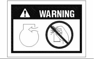
g00640926
Never spray Ether starting aids into the air inlet.
i02203039
General Hazard Information
Replace any damaged warning signs or missing
warning signs. If a warning sign is attached to a part
of the engine that is replaced, install a new warning
sign on the replacement part. Perkins dealers or
Perkins distributors can provide new warning signs.
Do not work on the engine and do not operate the
engine unless the instructions and warnings in the
Operation and Maintenance Manual are understood.
Correct care is your responsibility. Failure to follow
the instructions or failure to heed the warnings could
result in injury or in death.
The warning labels that may be found on the engine
are illustrated and described.
g00104545
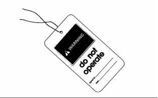
Illustration 1
Attach a “Do Not Operate” warning tag or a similar
warning tag to the start switch or to the controls
before you service the equipment or before you
repair the equipment.
This document has been printed from SPI². Not for Resale
![]()
![]()
![]()
![]()
6
SEBU8121
Safety Section
General Hazard Information
The maximum air pressure for cleaning purposes
must be below 205 kPa (30 psi). The maximum
water pressure for cleaning purposes must be below
275 kPa (40 psi).
Fluid Penetration
Pressure can be trapped in the hydraulic circuit long
after the engine has been stopped. The pressure can
cause hydraulic fluid or items such as pipe plugs to
escape rapidly if the pressure is not relieved correctly.
Do not remove any hydraulic components or parts
until pressure has been relieved or personal injury
may occur. Do not disassemble any hydraulic
components or parts until pressure has been relieved
or personal injury may occur. Refer to the OEM
information for any procedures that are required to
relieve the hydraulic pressure.
g00702020
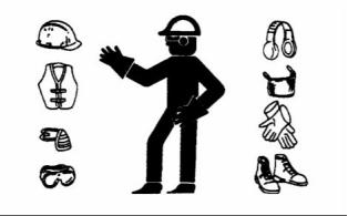
Illustration 2
Wear a hard hat, protective glasses, and other
protective equipment, as required.
Do not wear loose clothing or jewelry that can snag
on controls or on other parts of the engine.
Make sure that all protective guards and all covers
are secured in place on the engine.
Keep the engine free from foreign material. Remove
debris, oil, tools, and other items from the deck, from
walkways, and from steps.
Never put maintenance fluids into glass containers.
Drain all liquids into a suitable container.
Obey all local regulations for the disposal of liquids.
g00687600
Use all cleaning solutions with care. Report all
necessary repairs.
Illustration 3
Always use a board or cardboard when you check
for a leak. Leaking fluid that is under pressure can
penetrate body tissue. Fluid penetration can cause
serious injury and possible death. A pin hole leak can
cause severe injury. If fluid is injected into your skin,
you must get treatment immediately. Seek treatment
from a doctor that is familiar with this type of injury.
Do not allow unauthorized personnel on the
equipment.
Note: Ensure that the power supply is disconnected
before you work on the bus bar or the glow plugs.
Unless you are instructed otherwise, perform
maintenance on the engine with the equipment in
the servicing position. Refer to the OEM information
for the procedure for placing the equipment in the
servicing position.
Containing Fluid Spillage
Care must be taken in order to ensure that fluids
are contained during performance of inspection,
maintenance, testing, adjusting and repair of the
engine. Make provision to collect the fluid with a
suitable container before any compartment is opened
or before any component is disassembled.
Pressure Air and Water
Pressurized air and/or water can cause debris
and/or hot water to be blown out. This could result in
personal injury.
• Only use the tools that are suitable for collecting
fluids and equipment that is suitable for collecting
fluids.
When pressurized air and/or water is used for
cleaning, wear protective clothing, protective shoes,
and eye protection. Eye protection includes goggles
or a protective face shield.
• Only use the tools that are suitable for containing
fluids and equipment that is suitable for containing
fluids.
This document has been printed from SPI². Not for Resale
![]()
![]()
![]()

SEBU8121
7
Safety Section
Burn Prevention
Obey all local regulations for the disposal of liquids.
i02203164
Fire Prevention and Explosion
Prevention
i02143195
Burn Prevention
Do not touch any part of an operating engine.
Allow the engine to cool before any maintenance
is performed on the engine. Relieve all pressure
in the air system, in the hydraulic system, in the
lubrication system, in the fuel system, or in the
cooling system before any lines, fittings or related
items are disconnected.
Coolant
When the engine is at operating temperature, the
engine coolant is hot. The coolant is also under
pressure. The radiator and all lines to the heaters or
to the engine contain hot coolant.
g00704000
Illustration 4
All fuels, most lubricants, and some coolant mixtures
are flammable.
Any contact with hot coolant or with steam can cause
severe burns. Allow cooling system components to
cool before the cooling system is drained.
Flammable fluids that are leaking or spilled onto hot
surfaces or onto electrical components can cause
a fire. Fire may cause personal injury and property
damage.
Check the coolant level after the engine has stopped
and the engine has been allowed to cool.
Ensure that the filler cap is cool before removing the
filler cap. The filler cap must be cool enough to touch
with a bare hand. Remove the filler cap slowly in
order to relieve pressure.
A flash fire may result if the covers for the engine
crankcase are removed within fifteen minutes after
an emergency shutdown.
Determine whether the engine will be operated in an
environment that allows combustible gases to be
drawn into the air inlet system. These gases could
cause the engine to overspeed. Personal injury,
property damage, or engine damage could result.
Cooling system conditioner contains alkali. Alkali can
cause personal injury. Do not allow alkali to contact
the skin, the eyes, or the mouth.
Oils
If the application involves the presence of combustible
gases, consult your Perkins dealer and/or your
Perkins distributor for additional information about
suitable protection devices.
Hot oil and hot lubricating components can cause
personal injury. Do not allow hot oil to contact the
skin. Also, do not allow hot components to contact
the skin.
Remove all flammable combustible materials or
conductive materials such as fuel, oil, and debris from
the engine. Do not allow any flammable combustible
materials or conductive materials to accumulate on
the engine.
Batteries
Electrolyte is an acid. Electrolyte can cause personal
injury. Do not allow electrolyte to contact the skin or
the eyes. Always wear protective glasses for servicing
batteries. Wash hands after touching the batteries
and connectors. Use of gloves is recommended.
Store fuels and lubricants in correctly marked
containers away from unauthorized persons. Store
oily rags and any flammable materials in protective
containers. Do not smoke in areas that are used for
storing flammable materials.
Do not expose the engine to any flame.
This document has been printed from SPI². Not for Resale
![]()
![]()

8
SEBU8121
Safety Section
Fire Prevention and Explosion Prevention
Exhaust shields (if equipped) protect hot exhaust
components from oil or fuel spray in case of a line,
a tube, or a seal failure. Exhaust shields must be
installed correctly.
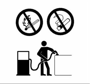
Use caution when you are refueling an engine. Do
not smoke while you are refueling an engine. Do not
refuel an engine near open flames or sparks. Always
stop the engine before refueling.
Do not weld on lines or tanks that contain flammable
fluids. Do not flame cut lines or tanks that contain
flammable fluid. Clean any such lines or tanks
thoroughly with a nonflammable solvent prior to
welding or flame cutting.
Wiring must be kept in good condition. All electrical
wires must be correctly routed and securely attached.
Check all electrical wires daily. Repair any wires
that are loose or frayed before you operate the
engine. Clean all electrical connections and tighten
all electrical connections.
Eliminate all wiring that is unattached or unnecessary.
Do not use any wires or cables that are smaller than
the recommended gauge. Do not bypass any fuses
and/or circuit breakers.
Arcing or sparking could cause a fire. Secure
connections, recommended wiring, and correctly
maintained battery cables will help to prevent arcing
or sparking.
g00704135
Illustration 6
Gases from a battery can explode. Keep any open
flames or sparks away from the top of a battery. Do
not smoke in battery charging areas.
Inspect all lines and hoses for wear or for
deterioration. The hoses must be correctly routed.
The lines and hoses must have adequate support
and secure clamps. Tighten all connections to the
recommended torque. Leaks can cause fires.
Never check the battery charge by placing a metal
object across the terminal posts. Use a voltmeter or
a hydrometer.
Oil filters and fuel filters must be correctly installed.
The filter housings must be tightened to the correct
torque.
Incorrect jumper cable connections can cause
an explosion that can result in injury. Refer to
the Operation Section of this manual for specific
instructions.
Do not charge a frozen battery. This may cause an
explosion.
The batteries must be kept clean. The covers
(if equipped) must be kept on the cells. Use the
recommended cables, connections, and battery box
covers when the engine is operated.
Fire Extinguisher
Make sure that a fire extinguisher is available. Be
familiar with the operation of the fire extinguisher.
Inspect the fire extinguisher and service the fire
extinguisher regularly. Obey the recommendations
on the instruction plate.
g00704059
Illustration 5
This document has been printed from SPI². Not for Resale
![]()
![]()
![]()

SEBU8121
9
Safety Section
Crushing Prevention and Cutting Prevention
Lines, Tubes and Hoses
Chips or other debris may fly off objects when objects
are struck. Before objects are struck, ensure that no
one will be injured by flying debris.
Do not bend high pressure lines. Do not strike high
pressure lines. Do not install any lines that are bent
or damaged.
i02157341
Before Starting Engine
Repair any lines that are loose or damaged. Leaks
can cause fires. Consult your Perkins dealer or your
Perkins distributor for repair or for replacement parts.
Check lines, tubes and hoses carefully. Do not use
your bare hand to check for leaks. Use a board or
cardboard to check for leaks. Tighten all connections
to the recommended torque.
NOTICE
For initial start-up of a new or rebuilt engine, and for
start-up of an engine that has been serviced, make
provision to shut the engine off should an overspeed
occur. This may be accomplished by shutting off the
air and/or fuel supply to the engine.
Replace the parts if any of the following conditions
are present:
• End fittings are damaged or leaking.
• Outer coverings are chafed or cut.
• Wires are exposed.
Overspeed shutdown should occur automatically.
If automatic shutdown does not occur, press the
emergency stop button in order to cut the fuel and/or
air to the engine.
Inspect the engine for potential hazards.
• Outer coverings are ballooning.
• Flexible part of the hoses are kinked.
• Outer covers have embedded armoring.
• End fittings are displaced.
Before starting the engine, ensure that no one is on,
underneath, or close to the engine. Ensure that the
area is free of personnel.
If equipped, ensure that the lighting system for the
engine is suitable for the conditions. Ensure that all
lights work correctly, if equipped.
Make sure that all clamps, guards, and heat shields
are installed correctly. During engine operation, this
will help to prevent vibration, rubbing against other
parts, and excessive heat.
All protective guards and all protective covers must
be installed if the engine must be started in order
to perform service procedures. To help prevent an
accident that is caused by parts in rotation, work
around the parts carefully.
i02143194
Crushing Prevention and
Cutting Prevention
Do not bypass the automatic shutoff circuits. Do not
disable the automatic shutoff circuits. The circuits are
provided in order to help prevent personal injury. The
circuits are also provided in order to help prevent
engine damage.
Support the component correctly when work beneath
the component is performed.
See the Service Manual for repairs and for
adjustments.
Unless other maintenance instructions are provided,
never attempt adjustments while the engine is
running.
i02207232
Engine Starting
Stay clear of all rotating parts and of all moving
parts. Leave the guards in place until maintenance
is performed. After the maintenance is performed,
reinstall the guards.
Keep objects away from moving fan blades. The fan
blades will throw objects or cut objects.
Do not use aerosol types of starting aids such as
ether. Such use could result in an explosion and
personal injury.
When objects are struck, wear protective glasses in
order to avoid injury to the eyes.
This document has been printed from SPI². Not for Resale
![]()
![]()
![]()
![]()
![]()
10
SEBU8121
Safety Section
Engine Stopping
If a warning tag is attached to the engine start switch
or to the controls, DO NOT start the engine or move
the controls. Consult with the person that attached
the warning tag before the engine is started.
Use the Emergency Stop Button (if equipped) ONLY
in an emergency situation. Do not use the Emergency
Stop Button for normal engine stopping. After an
emergency stop, DO NOT start the engine until the
problem that caused the emergency stop has been
corrected.
All protective guards and all protective covers must
be installed if the engine must be started in order
to perform service procedures. To help prevent an
accident that is caused by parts in rotation, work
around the parts carefully.
Stop the engine if an overspeed condition occurs
during the initial start-up of a new engine or an engine
that has been overhauled. This may be accomplished
by shutting off the fuel supply to the engine and/or
shutting off the air supply to the engine.
Start the engine from the operator’s compartment or
from the engine start switch.
Always start the engine according to the procedure
that is described in the Operation and Maintenance
Manual, “Engine Starting” topic in the Operation
Section. Knowing the correct procedure will help to
prevent major damage to the engine components.
Knowing the procedure will also help to prevent
personal injury.
i02176668
Electrical System
Never disconnect any charging unit circuit or battery
circuit cable from the battery when the charging unit
is operating. A spark can cause the combustible
gases that are produced by some batteries to ignite.
To ensure that the jacket water heater (if equipped)
and/or the lube oil heater (if equipped) is working
correctly, check the water temperature gauge and the
oil temperature gauge during the heater operation.
To help prevent sparks from igniting combustible
gases that are produced by some batteries, the
negative “−” jump start cable should be connected
last from the external power source to the negative
“−” terminal of the starting motor. If the starting motor
is not equipped with a negative “−” terminal, connect
the jump start cable to the engine block.
Engine exhaust contains products of combustion
which can be harmful to your health. Always start the
engine and operate the engine in a well ventilated
area. If the engine is started in an enclosed area,
vent the engine exhaust to the outside.
Check the electrical wires daily for wires that are
loose or frayed. Tighten all loose electrical wires
before the engine is started. Repair all frayed
electrical wires before the engine is started. See
the Operation and Maintenance Manual for specific
starting instructions.
Note: The engine is equipped with an automatic
device for cold starting for normal conditions of
operation. If the engine will be operated in very cold
conditions, then an extra cold starting aid may be
required. Normally, the engine will be equipped with
the correct type of starting aid for your region of
operation.
Grounding Practices
The engines are equipped with a glow plug starting
aid in each individual cylinder that heats the intake
air in order to improve starting.
Correct grounding for the engine electrical system
is necessary for optimum engine performance
and reliability. Incorrect grounding will result in
uncontrolled electrical circuit paths and in unreliable
electrical circuit paths.
i01928905
Engine Stopping
Uncontrolled electrical circuit paths can result in
damage to main bearings, to crankshaft bearing
journal surfaces, and to aluminum components.
Stop the engine according to the procedure in
the Operation and Maintenance Manual, “Engine
Stopping (Operation Section)” in order to avoid
overheating of the engine and accelerated wear of
the engine components.
Engines that are installed without engine-to-frame
ground straps can be damaged by electrical
discharge.
To ensure that the engine and the engine electrical
systems function correctly, an engine-to-frame
ground strap with a direct path to the battery must be
used. This path may be provided by way of a direct
engine ground to the frame.
This document has been printed from SPI². Not for Resale
![]()
SEBU8121
11
Safety Section
Engine Electronics
All grounds should be tight and free of corrosion. The
engine alternator must be grounded to the negative
“-” battery terminal with a wire that is adequate to
handle the full charging current of the alternator.
i01885770
Engine Electronics
Tampering with the electronic system installation
or the OEM wiring installation can be dangerous
and could result in personal injury or death and/or
engine damage.
This engine has a comprehensive, programmable
Engine Monitoring System. The Electronic Control
Module (ECM) has the ability to monitor the engine
operating conditions. If any of the engine parameters
extend outside an allowable range, the ECM will
initiate an immediate action.
The following actions are available for engine
monitoring control: WARNING, DERATE, and
SHUTDOWN. These engine monitoring modes have
the ability to limit engine speed and/or the engine
power.
• Engine Coolant Temperature
• Engine Oil Pressure
• Engine Speed
• Fuel Temperature
• Intake Manifold Air Temperature
• System Voltage
The Engine Monitoring package can vary for different
engine models and different engine applications.
However, the monitoring system and the engine
monitoring control will be similar for all engines.
Note: Many of the engine control systems and display
modules that are available for Perkins Engines will
work in unison with the Engine Monitoring System.
Together, the two controls will provide the engine
monitoring function for the specific engine application.
Refer to the Electronic Troubleshooting Manual for
more information on the Engine Monitoring System.
This document has been printed from SPI². Not for Resale
![]()
![]()
![]()
12
SEBU8121
Product Information Section
General Information
Product Information
Section
General Information
i01889424
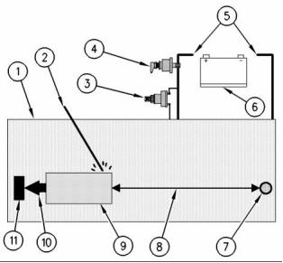
Welding on Engines with
Electronic Controls
NOTICE
Proper welding procedures are necessary in order
to avoid damage to the engine’s ECM, sensors, and
associated components. When possible, remove the
component from the unit and then weld the compo-
nent. If removal of the component is not possible,
the following procedure must be followed when you
weld with a unit that is equipped with an Electronic
Engine. The following procedure is considered to be
the safest procedure to weld a component. This pro-
cedure should provide a minimum risk of damage to
electronic components.
g00765012
Illustration 7
Use the example above. The current flow from the welder to
the ground clamp of the welder will not cause damage to any
associated components.
(1) Engine
(2) Welding rod
(3) Keyswitch in the OFF position
(4) Battery disconnect switch in the open position
(5) Disconnected battery cables
(6) Battery
NOTICE
(7) Electrical/Electronic component
(8) Maximum distance between the component that is being
welded and any electrical/electronic component
(9) The component that is being welded
(10) Current path of the welder
(11) Ground clamp for the welder
Do not ground the welder to electrical components
such as the ECM or sensors. Improper grounding can
cause damage to the drive train bearings, hydraulic
components, electrical components, and other com-
ponents.
4. Connect the welding ground cable directly to the
part that will be welded. Place the ground cable as
close as possible to the weld in order to reduce the
possibility of welding current damage to bearings,
hydraulic components, electrical components, and
ground straps.
Clamp the ground cable from the welder to the com-
ponent that will be welded. Place the clamp as close
as possible to the weld. This will help reduce the pos-
sibility of damage.
1. Stop the engine. Turn the switched power to the
Note: If electrical/electronic components are used
as a ground for the welder, or electrical/electronic
components are located between the welder ground
and the weld, current flow from the welder could
severely damage the component.
OFF position.
2. Disconnect the negative battery cable from the
battery. If a battery disconnect switch is provided,
open the switch.
5. Protect the wiring harness from welding debris
3. Disconnect the J1/P1 connectors from the ECM.
Move the harness to a position that will not allow
the harness to accidentally move back and make
contact with any of the ECM pins.
and spatter.
6. Use standard welding practices to weld the
materials.
This document has been printed from SPI². Not for Resale
![]()
![]()
![]()
![]()
![]()
![]()
![]()
SEBU8121
13
Product Information Section
Model Views
Model Views
i02247468
Model View Illustrations
1104 Engine Views
g01131700
Illustration 8
Left side view of the 1104 engine
Typical example of the 1104 engine
This document has been printed from SPI². Not for Resale
![]()
![]()

14
SEBU8121
Product Information Section
Model Views
(1) Fuel lines
(8) Engine oil filter
(2) Fuel priming pump
(9) Water pump
(3) Fuel filter
(10) Crankshaft pulley
(4) Machine interface connector (MIC)
(5) Speed/timing sensor
(6) Electronic fuel injection pump
(7) Engine oil pressure sensor
(11) Alternator
(12) Engine coolant temperature sensor
(13) Voltage load protection module
(14) Electronic control module (ECM)
g01131701
Illustration 9
Right side view of the 1104 engine
Typical example of the 1104 engine
(1) Exhaust elbow
(2) Turbocharger
(3) Wastegate actuator
(4) Starter motor
(5) Flywheel housing
This document has been printed from SPI². Not for Resale
![]()
![]()

SEBU8121
15
Product Information Section
Model Views
i02247483
Table 1
Engine Description
1104 Electronic Engine Specifications
Number of Cylinders
Bore
4 In-Line
105 mm (4.134 inch)
127 mm (5.0 inch)
The Perkins1104 Electronic Engine is designed for
the following applications: machine and industrial
mobile equipment. The engines are available in the
following types of aspiration:
Stroke
Aspiration
Turbocharged, aftercooled
Turbocharged
Naturally aspirated
• Turbocharged aftercooled
• Turbocharged
Compression Ratio
NA 19.25:1 NA
T 18.23:1 T, TA
Displacement
4.4 L (268 in )
3
1-3-4-2
• Naturally aspirated
Firing Order
Rotation (flywheel end)
Valve Lash Setting (Inlet)
Counterclockwise
Engine Specifications
0.20 mm (0.008 inch)
Note: The front end of the engine is opposite the
flywheel end of the engine. The left and the right
sides of the engine are determined from the flywheel
end. The number 1 cylinder is the front cylinder.
Valve Lash Setting
(Exhaust)
0.45 mm (0.018 inch)
Electronic Engine Features
The Perkins 1104 Electronic Engine is designed with
electronic controls. The integral on board computer
controls the operation of the engine. Current
operating conditions are monitored. The Electronic
Control Module (ECM) controls the response of the
engine to these conditions and to the demands of the
operator. These conditions and operator demands
determine the precise control of fuel injection by the
ECM. The electronic engine control system provides
the following features:
• Engine monitoring
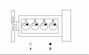
g00984281
• Engine speed governing
• Cold start strategy
Illustration 10
Typical example
1104 Electronic engine
(A) Inlet valves
• Automatic air/fuel ratio control
• Torque rise shaping
(B) Exhaust valves
• Automatic altitude compensation
• Fuel temperature compensation
• Injection timing control
• System diagnostics
For more information on electronic engine features,
refer to the Operation and Maintenance Manual,
“Features and Controls” topic (Operation Section).
This document has been printed from SPI². Not for Resale
![]()
![]()

16
SEBU8121
Product Information Section
Model Views
Engine Diagnostics
Engine Service Life
The Perkins 1104 engine has built-in diagnostics
in order to ensure that all of the components are
functioning properly. The operator will be informed of
any change to a programmed limit. The operator will
be alerted to the condition by a “Stop or Warning”
lamp that may be mounted on the dashboard or
on the control panel. Under certain conditions, the
engine horsepower and the vehicle speed may be
limited. The electronic service tool may be used to
display the diagnostic codes.
Engine efficiency and maximum utilization of engine
performance depend on the adherence to proper
operation and maintenance recommendations. In
addition, use recommended fuels, coolants and
lubricants. Use the Operation and Maintenance
Manual as a guide for required engine maintenance.
Expected engine life is generally predicted by the
average power that is demanded. The average power
that is demanded is based on fuel consumption of
the engine over a period of time. Reduced hours of
operation at full throttle and/or operating at reduced
throttle settings result in a lower average power
demand. Reduced hours of operation will increase
the length of operating time before an engine
overhaul is required.
There are three types of diagnostic codes: active,
logged, and event.
Most of the diagnostic codes are logged and stored
in the ECM. For additional information, refer to
the Operation and Maintenance Manual, “Engine
Diagnostics” topic (Operation Section).
The ECM provides an electronic governor that
controls the injector output in order to maintain the
desired engine rpm.
Engine Cooling and Lubrication
The cooling system consists of the following
components:
• Gear-driven centrifugal water pump
• Water temperature regulators which regulate the
engine coolant temperature
• Gear-driven oil pump (gear type)
• Oil cooler
The engine lubricating oil is supplied by a gear
type pump. The engine lubricating oil is cooled and
the engine lubricating oil is filtered. Bypass valves
provide unrestricted flow of lubrication oil to the
engine pa, rts when oil viscosity is high. Bypass valves
can also provide unrestricted flow of lubrication oil
to the engine parts if the oil cooler should become
plugged or if the oil filter element should become
plugged.
Engine efficiency, efficiency of emission controls, and
engine performance depend on adherence to proper
operation and maintenance recommendations.
Engine performance and efficiency also depend on
the use of recommended fuels, lubrication oils, and
coolants. Refer to the Operation and Maintenance
Manual, “Maintenance Interval Schedule” for more
information on maintenance items.
This document has been printed from SPI². Not for Resale
![]()
SEBU8121
17
Product Information Section
Product Identification Information
Product Identification
Information
i01940474
Serial Number Plate
i02280116
Engine Identification
Perkins engines are identified by a serial number.
This number is shown on a serial number plate that
is mounted on the left hand side of the engine block.
An example of an engine number is
RE12345U090001H.
RE __________________________________________Type of engine
RE12345____________________________Engine List Number
U ____________________________Built in the United Kingdom
090001 ___________________________Engine Serial Number
H _____________________________________Year of Manufacture
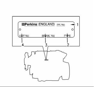
g00994966
Illustration 11
Perkins dealers need these numbers in order to
determine the components that were included with
the engine. This permits accurate identification of
replacement part numbers.
Typical serial number plate
(1) Temporary Parts List number
(2) Type
(3) Serial number
(4) List number
The Serial Number Plate is located on the left side of
the cylinder block behind the high pressure pipes of
the Fuel injection pump.
The following information is stamped on the Serial
Number Plate: Engine serial number, Model, and
Arrangement number.
i02164876
Reference Numbers
Information for the following items may be needed to
order parts. Locate the information for your engine.
Record the information in the appropriate space.
Make a copy of this list for a record. Keep the
information for future reference.
Record for Reference
Engine Model _______________________________________________
Engine Serial number _____________________________________
Engine Low Idle rpm ______________________________________
This document has been printed from SPI². Not for Resale
![]()
![]()
18
SEBU8121
Product Information Section
Product Identification Information
Engine Full Load rpm _____________________________________
Primary Fuel Filter _________________________________________
Water Separator Element ________________________________
Secondary Fuel Filter Element __________________________
Lubrication Oil Filter Element ___________________________
Auxiliary Oil Filter Element _______________________________
Total Lubrication System Capacity _____________________
Total Cooling System Capacity _________________________
Air Cleaner Element _______________________________________
Fan Drive Belt ______________________________________________
Alternator Belt ______________________________________________
i02272778
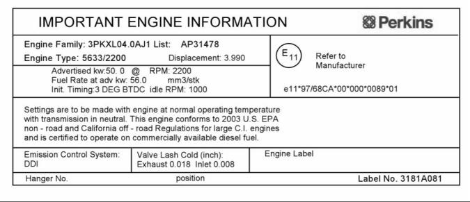
Emissions Certification Film
Label for compliant engines
g01127835
Illustration 12
Typical example
This label is installed on engines that comply with emissions.
This document has been printed from SPI². Not for Resale
![]()
![]()
SEBU8121
19
Operation Section
Lifting and Storage
Operation Section
Lifting and Storage
Some removals require lifting the fixtures in order to
obtain correct balance and safety.
To remove the engine ONLY, use the lifting eyes that
are on the engine.
Lifting eyes are designed and installed for specific
engine arrangements. Alterations to the lifting eyes
and/or the engine make the lifting eyes and the lifting
fixtures obsolete. If alterations are made, ensure
that correct lifting devices are provided. Consult
your Perkins dealer or your Perkins distributor for
information regarding fixtures for correct engine
lifting.
i02164186
Engine Lifting
i02248407
Engine Storage
If the engine will not be started for several weeks, the
lubricating oil will drain from the cylinder walls and
from the piston rings. Rust can form on the cylinder
walls. Rust on the cylinder walls will cause increased
engine wear and a reduction in engine service life.
Lubrication System
To help prevent excessive engine wear, use the
following guidelines:
Complete all of the lubrication recommendations that
are listed in this Operation and Maintenance Manual,
“Maintenance Interval Schedule” (Maintenance
Section).
If an engine is out of operation and if use of the engine
is not planned, special precautions should be made.
If the engine will be stored for more than one month,
a complete protection procedure is recommended.
g01097527
Illustration 13
NOTICE
Use the following guidelines :
Never bend the eyebolts and the brackets. Only load
the eyebolts and the brackets under tension. Remem-
ber that the capacity of an eyebolt is less as the angle
between the supporting members and the object be-
comes less than 90 degrees.
• Completely clean the outside of the engine.
• Drain the fuel system completely and refill
the system with preservative fuel.1772204
POWERPART Lay-Up 1 can be mixed with
the normal fuel in order to change the fuel into
preservative fuel.
When it is necessary to remove a component at an
angle, only use a link bracket that is properly rated for
the weight.
• If preservative fuel is not available, the fuel system
can be filled with normal fuel. This fuel must be
discarded at the end of the storage period together
with the fuel filter elements.
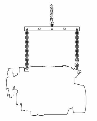
Use a hoist to remove heavy components. Use
an adjustable lifting beam to lift the engine. All
supporting members (chains and cables) should be
parallel to each other. The chains and cables should
be perpendicular to the top of the object that is being
lifted.
• Operate the engine until the engine reaches
normal operating temperature. Stop any leaks from
fuel, lubricating oil or air systems. Stop the engine
and drain the lubricating oil from the oil pan.
This document has been printed from SPI². Not for Resale
![]()
![]()
![]()
![]()
![]()
20
SEBU8121
Operation Section
Lifting and Storage
• Renew the canister(s) of the lubricating oil filter.
4. Open the tap or remove the drain plug at the
bottom of the radiator in order to drain the radiator.
If the radiator does not have a tap or a drain plug,
disconnect the hose at the bottom of the radiator.
• Fill the oil pan to the Full Mark on the dipstick
with new, clean lubricating oil. Add 1762811
POWERPART Lay-Up 2 to the oil in order to
protect the engine against corrosion. If 1762811
POWERPART Lay-Up 2 is not available, use a
preservative of the correct specification instead
of the lubricating oil. If a preservative is used,
this must be drained completely at the end of the
storage period and the oil pan must be refilled to
the correct level with normal lubricating oil.
5. Flush the cooling system with clean water.
6. Fit the drain plugs and the filler cap. Close the tap
or connect the radiator hose.
7. Fill the cooling system with an approved
antifreeze mixture because this gives protection
against corrosion. The maximum flow rate is 1 L
(0.2200 Imp gal) per minute in order to fill the
system.
Cooling System
To help prevent excessive engine wear, use the
following guidelines:
Note: Certain corrosion inhibitors could cause
damage to some engine components. Contact the
Service Department of Perkins for advice.
NOTICE
Do not drain the coolant while the engine is still hot and
the system is under pressure because dangerous hot
coolant can be discharged.
8. Operate the engine for a short period in order to
circulate the lubricating oil and the coolant in the
engine.
9. Disconnect the battery. Put the battery into safe
storage in a fully charged condition. Before the
battery is put into storage, protect the terminals
against corrosion.1734115 POWERPART Lay-Up
3 can be used on the terminals.
If freezing temperatures are expected, check the
cooling system for adequate protection against
freezing. See this Operation and Maintenance
Manual, “General Coolant Information” (Maintenance
Section).
10. Clean the crankcase breather if one is installed.
NOTICE
Seal the end of the pipe.
To prevent frost damage, ensure that all the coolant is
removed from the engine. This is important if the sys-
tem is drained after it has been flushed with water, or if
an antifreeze solution too weak to protect the system
from frost has been used.
11. Remove the fuel injector nozzles and spray
1762811
POWERPART Lay-Up 2 for one or two
seconds into each cylinder bore with the piston
at BDC.
12. Slowly rotate the crankshaft for one complete
revolution and then replace the fuel injector
nozzles.
Induction System
• Remove the air filter assembly. If necessary,
remove the pipes that are installed between
the air filter assembly and the turbocharger.
Spray 1762811 POWERPART Lay-Up 2 into the
turbocharger. The duration of the spray is printed
on the container. Seal the turbocharger with
waterproof tape.
g01003928
Illustration 14
Exhaust System
1. Ensure that the engine is on level ground.
2. Remove the filler cap of the cooling system.
• Remove the exhaust pipe. Spray 1762811
POWERP
ART Lay-Up 2 into the turbocharger. The
duration of the spray is printed on the container.
Seal the turbocharger with waterproof tape.
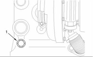
3. Remove the drain plug (1) from the side of the
cylinder block in order to drain the engine. Ensure
that the drain hole is not restricted.
This document has been printed from SPI². Not for Resale
![]()
![]()
![]()
![]()
![]()
![]()
SEBU8121
21
Operation Section
Lifting and Storage
General Items
• If the lubricating oil filler is installed on the rocker
cover, remove the filler cap. If the lubricating oil filler
cap is not installed on the rocker cover, remove
the rocker cover. Spray 1762811 POWERPART
Lay-Up 2 around the rocker shaft assembly.
Replace the filler cap or the rocker cover.
• Seal the vent of the fuel tank or the fuel filler cap
with waterproof tape.
• Remove the alternator drive belts and put the drive
belts into storage.
• In order to prevent corrosion, spray the engine with
1734115 POWERPART Lay-Up 3. Do not spray
the area inside the alternator.
When the engine protection has been completed in
accordance with these instructions, this ensures that
no corrosion will occur. Perkins are not responsible
for damage which may occur when an engine is in
storage after a period in service.
Your Perkins dealer or your Perkins distributor can
assist in preparing the engine for extended storage
periods.
This document has been printed from SPI². Not for Resale
![]()
22
SEBU8121
Operation Section
Gauges and Indicators
Gauges and Indicators
1. Reduce the load and the engine rpm.
2. Inspect the cooling system for leaks.
i02164190
3. Determine if the engine must be shut down
immediately or if the engine can be cooled by
reducing the load.
Gauges and Indicators
Tachometer – This gauge indicates engine
speed (rpm). When the throttle control lever
is moved to the full throttle position without
load, the engine is running at high idle. The engine is
running at the full load rpm when the throttle control
lever is at the full throttle position with maximum
rated load.
Your engine may not have the same gauges or all of
the gauges that are described. For more information
about the gauge package, see the OEM information.
Gauges provide indications of engine performance.
Ensure that the gauges are in good working order.
Determine the normal operating range by observing
the gauges over a period of time.
NOTICE
To help prevent engine damage, never exceed the
high idle rpm. Overspeeding can result in serious
damage to the engine. The engine can be operated
at high idle without damage, but should never be
allowed to exceed high idle rpm.
Noticeable changes in gauge readings indicate
potential gauge or engine problems. Problems may
also be indicated by gauge readings that change
even if the readings are within specifications.
Determine and correct the cause of any significant
change in the readings. Consult your Perkins dealer
or your Perkins distributor for assistance.
Ammeter – This gauge indicates the
amount of charge or discharge in the
NOTICE
battery charging circuit. Operation of the
indicator should be to the right side of “0” (zero).
If no oil pressure is indicated, STOP the engine. If
maximum coolant temperature is exceeded, STOP
the engine. Engine damage can result.
Fuel Level – This gauge indicates the fuel
level in the fuel tank. The fuel level gauge
operates when the “START/STOP” switch
is in the “ON” position.
Engine Oil Pressure – The oil pressure
should be greatest after a cold engine is
started. The typical engine oil pressure with
SAE10W30 is 207 to 413 kPa (30 to 60 psi) at rated
rpm.
Service Hour Meter – The gauge indicates
operating time of the engine.
A lower oil pressure is normal at low idle. If the load
is stable and the gauge reading changes, perform
the following procedure:
1. Remove the load.
2. Reduce engine speed to low idle.
3. Check and maintain the oil level.
Jacket Water Coolant Temperature –
Typical temperature range is 71 to 96°C
(160 to 205°F). The maximum allowable
temperature with the pressurized cooling system at
48 kPa (7 psi) is 110°C (230°F). Higher temperatures
may occur under certain conditions. The water
temperature reading may vary according to load. The
reading should never exceed the boiling point for the
pressurized system that is being used.
If the engine is operating above the normal range
and steam becomes apparent, perform the following
procedure:
This document has been printed from SPI². Not for Resale
![]()
![]()
![]()
![]()
![]()
![]()
![]()
![]()
![]()
![]()
![]()
SEBU8121
23
Operation Section
Features and Controls
Features and Controls
“Warning”
The “Warning” lamp and the warning signal (orange
lamp) turn “ON” and the warning signal is activated
continuously in order to alert the operator that one or
more of the engine parameters is not within normal
operating range.
i02259828
Monitoring System
“Warning/Derate”
The “Diagnostic” lamp turns “ON” and the warning
signal (red lamp) is activated. After the warning, the
engine power will be derated. The warning lamp will
begin to flash when the derating occurs.
If the Shutdown mode has been selected and the
warning indicator activates, engine shutdown may
take as little as 20 seconds from the time the warn-
ing indicator is activated. Depending on the ap-
plication, special precautions should be taken to
avoid personal injury. The engine can be restarted
following shutdown for emergency maneuvers, if
necessary.
The engine will be derated if the engine exceeds
preset operational limits. The engine derate is
achieved by restricting the amount of fuel that is
available for each injection. The amount of this
reduction of fuel is dependent on the severity of the
fault that has caused the engine derate, typically up
to a limit of 50%. This reduction in fuel results in a
predetermined reduction in engine power.
NOTICE
The Engine Monitoring System is not a guarantee
against catastrophic failures. Programmed delays
and derate schedules are designed to minimize false
alarms and provide time for the operator to stop the
engine.
“Warning/Derate/Shutdown”
The “Diagnostic” lamp turns “ON” and the warning
signal (red lamp) is activated. After the warning,
the engine power will be derated. The engine will
continue at the rpm of the set derate until a shutdown
of the engine occurs. The engine can be restarted
after a shutdown for use in an emergency.
The following parameters are monitored:
• Coolant temperature
• Intake manifold air temperature
• Intake manifold air pressure
• Oil pressure
A shutdown of the engine may occur in as little
as 20 seconds. The engine can be restarted after
a shutdown for use in an emergency. However,
the cause of the initial shutdown may still exist.
The engine may shut down again in as little as 20
seconds.
• Fuel temperature
• Engine speed/timing
If there is a signal for low oil pressure or for coolant
temperature, there will be a two second delay in
order to verify the condition.
Programmable Options and
Systems Operation
For each of the programmed modes, refer to
Troubleshooting Guide, “Indicator Lamps” for more
information on Indicator Lamps.
For more information or assistance for repairs, consult
your Perkins dealer or your Perkins distributor.
If the Warning/Derate/Shutdown mode has been
selected and the warning indicator activates,
bring the engine to a stop whenever possible. De-
pending on the application, special precautions
should be taken to avoid personal injury.
The engine can be programmed to the following
modes:
This document has been printed from SPI². Not for Resale
![]()
![]()
![]()
![]()
![]()
![]()
![]()
24
SEBU8121
Operation Section
Features and Controls
i02259829
Sensors and Electrical
Components
Sensor Locations for the 1104
Engine
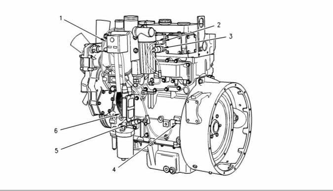
g00894185
Illustration 15
Left side view of the 1104 engine
Typical example of a 1104 engine
(1) Electronic control module (ECM)
(2) Intake manifold temperature sensor
(3) Intake manifold pressure sensor
(4) Speed/timing sensor
(5) Engine oil pressure sensor
(6) Machine interface connector
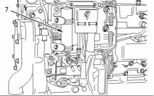
g00915275
Illustration 16
(7) Typical location of the voltage load protection module by the
ECM
This document has been printed from SPI². Not for Resale
![]()
![]()
![]()
SEBU8121
25
Operation Section
Features and Controls
g00915291
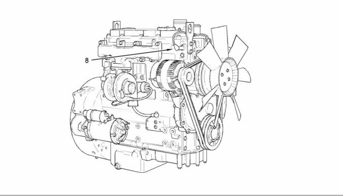
Illustration 17
Right side view of the 1104 engine
Typical example of a 1104 engine
(8) Engine coolant temperature sensor
Failure of Sensors
Engine Oil Pressure Sensor
All Sensors
The engine oil pressure sensor is an absolute
pressure sensor that measures the engine oil
pressure in the main oil gallery. The engine oil
pressure sensor detects engine oil pressure for
diagnostic purposes. The engine oil pressure sensor
sends a signal to the ECM.
A failure of any of the sensors may be caused by one
of the following malfunctions:
• Sensor output is open.
• Sensor output is shorted to “- battery” or “+ battery”.
Intake Manifold Temperature
Sensor
• Measured reading of the sensor is out of the
specification.
The intake manifold temperature sensor measures
the inlet air temperature. A signal is sent to the
Electronic Control Module (ECM). The intake
manifold temperature sensor is also used by the
ECM to determine initiation of the Cold Start Strategy
and control for appropriate start of injection timing
while the engine is warming up.
Intake Manifold Pressure Sensor
The intake manifold pressure sensor provides a
signal which corresponds to the intake manifold
pressure to the ECM. The ECM can control injection
timing and the amount of fuel that is injected.
When the throttle is increased and when the engine
demands more fuel, the fuel limit is controlled in order
to reduce overall smoke levels of the engine exhaust.
This document has been printed from SPI². Not for Resale
![]()
![]()
26
SEBU8121
Operation Section
Features and Controls
Coolant Temperature Sensor
The coolant temperature sensor monitors the engine
coolant temperature. The output of the ECM can
indicate a high coolant temperature through a relay
or a lamp. The coolant temperature sensor is used
by the ECM to determine initiation of the Cold Start
Condition and control for appropriate start of injection
timing while the engine is warming up.
Speed/Timing Sensor
If the ECM does not receive a signal from the primary
speed/timing sensor the “DIAGNOSTIC” lamp will
indicate a diagnostic fault code which will be logged
in the ECM memory.
If the ECM does not receive a signal from the primary
speed/timing sensor, the ECM will read the signal
from the secondary speed/timing sensor. The ECM
continually checks in order to determine if there is a
signal from both sensors. If either sensor fails, the
faulty sensor should be replaced.
Intermittent failure of the sensors will cause erratic
engine control.
Throttle Position Sensor
The throttle position sensor (TPS) eliminates the
mechanical throttle and governor linkages. The TPS
interprets the position of the throttle lever into an
electrical signal that is sent to the ECM. The throttle
position signal and the engine speed/timing signal
are processed by the ECM in order to precisely
control engine speed.
This document has been printed from SPI². Not for Resale
![]()
SEBU8121
27
Operation Section
Engine Diagnostics
Engine Diagnostics
i01902949
Fault Logging
i01902950
Self-Diagnostics
The system provides the capability of Fault Logging.
When the Electronic Control Module (ECM)
generates an active diagnostic code, the code will
be logged in the memory of the ECM. The codes
that have been logged by the ECM can be identified
by the electronic service tool. The active codes that
have been logged will be cleared when the fault
has been rectified or the fault is no longer active.
The following logged faults can not be cleared from
the memory of the ECM without using a factory
password: Overspeed, low engine oil pressure, and
high engine coolant temperature.
Perkins Electronic Engines have the capability to
perform a self-diagnostics test. When the system
detects an active problem, a diagnostic lamp
is activated. Diagnostic codes will be stored in
permanent memory in the Electronic Control Module
(ECM). The diagnostic codes can be retrieved
by using the electronic service tool. Refer to
Troubleshooting Guide, “Electronic Service Tools” for
further information.
Some installations have electronic displays that
provide direct readouts of the engine diagnostic
codes. Refer to the manual that is provided
by the OEM for more information on retrieving
engine diagnostic codes. Alternatively refer to the
Troubleshooting Guide, “Indicator Lamps” for further
information.
i01902951
Engine Operation with Active
Diagnostic Codes
If a diagnostic lamp illuminates during normal engine
operation, the system has identified a situation that is
not within the specification. Use the electronic service
tool to check the active diagnostic codes.
Active codes represent problems that currently exist.
These problems should be investigated first.
Logged codes represent the following items:
• Intermittent problems
The active diagnostic code should be investigated.
The cause of the problem should be corrected as
soon as possible. If the cause of the active diagnostic
code is repaired and there is only one active
diagnostic code, the diagnostic lamp will turn off.
• Recorded events
• Performance history
Operation of the engine and performance of the
engine can be limited as a result of the active
diagnostic code that is generated. Acceleration rates
may be significantly slower and power outputs may be
automatically reduced. Refer to the Troubleshooting
Guide, “Troubleshooting with a Diagnostic Code” for
more information on the relationship between each
active diagnostic code and the possible effect on
engine performance.
The problems may have been repaired since the
logging of the code. These codes do not indicate that
a repair is needed. The codes are guides or signals
when a situation exists. Codes may be helpful to
troubleshoot problems.
When the problems have been corrected, the
corresponding logged fault codes should be cleared.
i01902948
Diagnostic Lamp
A diagnostic lamp is used to indicate the existence
of an active fault. Refer to the Troubleshooting
Guide, “Indicator Lamps” for more information. A fault
diagnostic code will remain active until the problem
is repaired. The diagnostic code may be retrieved
by using the electronic service tool. Refer to the
Troubleshooting Guide, “Electronic Service Tools”
for more information.
This document has been printed from SPI². Not for Resale
![]()
28
SEBU8121
Operation Section
Engine Diagnostics
i01902995
Engine Operation with
Intermittent Diagnostic Codes
If a diagnostic lamp illuminates during normal engine
operation and the diagnostic lamp shuts off, an
intermittent fault may have occurred. If a fault has
occurred, the fault will be logged into the memory of
the Electronic Control Module (ECM).
In most cases, it is not necessary to stop the engine
because of an intermittent code. However, the
operator should retrieve the logged fault codes
and the operator should reference the appropriate
information in order to identify the nature of the event.
The operator should log any observation that could
have caused the lamp to light.
• Low power
• Limits of the engine speed
• Excessive smoke, etc
This information can be useful to help troubleshoot
the situation. The information can also be used for
future reference. For more information on diagnostic
codes, refer to the Troubleshooting Guide for this
engine.
This document has been printed from SPI². Not for Resale
![]()
SEBU8121
29
Operation Section
Engine Starting
Engine Starting
• Do not start the engine or move any of the controls
if there is a “DO NOT OPERATE” warning tag or
similar warning tag attached to the start switch or
to the controls.
i02194223
Before Starting Engine
• Ensure that the areas around the rotating parts are
clear.
• All of the guards must be put in place. Check for
damaged guards or for missing guards. Repair
any damaged guards. Replace damaged guards
and/or missing guards.
Before the engine is started, perform the required
daily maintenance and any other periodic
maintenance that is due. Refer to the Operation
and Maintenance Manual, “Maintenance Interval
Schedule” for more information.
•
Disconnect any battery chargers that are not
protected against the high current drain that
is created when the electric starting motor is
engaged. Check electrical cables and check the
battery for poor connections and for corrosion.
• For the maximum service life of the engine, make a
thorough inspection within the engine compartment
before the engine is started. Look for the following
items: oil leaks, coolant leaks, loose bolts, and
excessive dirt and/or grease. Remove any excess
dirt and/or grease buildup. Repair any faults that
were identified during the inspection.
•
Reset all of the shutoffs or alarm components (if
equipped).
• Check the engine lubrication oil level. Maintain the
oil level between the “ADD” mark and the “FULL”
mark on the engine oil level gauge.
• Inspect the cooling system hoses for cracks and
for loose clamps.
• Inspect the alternator and accessory drive belts for
cracks, breaks, and other damage.
• Check the coolant level. Observe the coolant level
in the header tank (if equipped). Maintain the
coolant level to the “FULL” mark on the header
tank.
• Inspect the wiring for loose connections and for
worn wires or frayed wires.
• If the engine is not equipped with a header tank
maintain the coolant level within 13 mm (0.5 inch)
of the bottom of the filler pipe. If the engine is
equipped with a sight glass, maintain the coolant
level in the sight glass.
• Check the fuel supply. Drain water from the water
separator (if equipped). Open the fuel supply valve
(if equipped).
NOTICE
• Observe the air cleaner service indicator (if
equipped). Service the air cleaner when the yellow
diaphragm enters the red zone, or when the red
piston locks in the visible position.
All valves in the fuel return line must be open before
and during engine operation to help prevent high fuel
pressure. High fuel pressure may cause filter housing
failure or other damage.
• Ensure that any equipment that is driven by the
engine has been disengaged from the engine.
Minimize electrical loads or remove any electrical
loads.
If the engine has not been started for several weeks,
fuel may have drained from the fuel system. Air
may have entered the filter housing. Also, when fuel
filters have been changed, some air pockets will be
trapped in the engine. In these instances, prime the
fuel system. Refer to the Operation and Maintenance
Manual, “Fuel System - Prime” for more information
on priming the fuel system.
i02272761
Starting the Engine
Note: Do not adjust the engine speed control during
start-up. The electronic control module (ECM) will
control the engine speed during start-up.
Engine exhaust contains products of combustion
which may be harmful to your health. Always start
and operate the engine in a well ventilated area
and, if in an enclosed area, vent the exhaust to the
outside.
Starting a Cold Engine
1. Disengage any equipment that is driven by the
engine.
This document has been printed from SPI². Not for Resale
![]()
![]()
![]()
![]()
![]()
30
SEBU8121
Operation Section
Engine Starting
2. Turn the keyswitch to the RUN position. Leave the
i01903593
keyswitch in the RUN position for 20 seconds.
Starting with Jump Start
Cables
3. Turn the keyswitch to the START position in order
to engage the electric starting motor and crank
the engine.
NOTICE
Do not engage the starting motor when flywheel is
turning. Do not start the engine under load.
Improper jump start cable connections can cause
an explosion resulting in personal injury.
If the engine fails to start within 30 seconds, release
the starter switch or button and wait two minutes to
allow the starting motor to cool before attempting to
start the engine again.
Prevent sparks near the batteries. Sparks could
cause vapors to explode. Do not allow jump start
cable ends to contact each other or the engine.
4. Allow the keyswitch to return to the RUN position
Note: If it is possible, first diagnose the reason
for the starting failure. Refer to Troubleshooting,
“Engine Will Not Crank and Engine Cranks But
Will Not Start” for further information. Make any
necessary repairs. If the engine will not start only
due to the condition of the battery, either charge the
battery, or start the engine with jump start cables.
The condition of the battery can be rechecked
after the engine has been switched OFF.
after the engine starts.
5. Repeat step 2 through step 4 if the engine fails
to start.
Starting a Warm Engine
1. Disengage any equipment that is driven by the
engine.
2. Turn the keyswitch to the START position in order
to engage the electric starting motor and crank
the engine.
NOTICE
Using a battery source with the same voltage as the
electric starting motor. Use ONLY equal voltage for
jump starting. The use of higher voltage will damage
the electrical system.
NOTICE
Do not engage the starting motor when flywheel is
turning. Do not start the engine under load.
Do not reverse the battery cables. The alternator can
be damaged. Attach ground cable last and remove
first.
If the engine fails to start within 30 seconds, release
the starter switch or button and wait two minutes to
allow the starting motor to cool before attempting to
start the engine again.
When using an external electrical source to start the
engine, turn the generator set control switch to the
“OFF” position. Turn all electrical accessories OFF be-
fore attaching the jump start cables.
3. Allow the keyswitch to return to the RUN position
after the engine starts.
Ensure that the main power switch is in the OFF posi-
tion before attaching the jump start cables to the en-
gine being started.
4. Repeat step 2 and step 3 if the engine fails to start.
1. Turn the start switch on the stalled engine to the
OFF position. Turn off all the engine’s accessories.
2. Connect one positive end of the jump start cable
to the positive cable terminal of the discharged
battery. Connect the other positive end of the jump
start cable to the positive cable terminal of the
electrical source.
This document has been printed from SPI². Not for Resale
![]()
![]()
![]()
![]()
![]()
![]()
![]()
![]()
![]()
SEBU8121
31
Operation Section
Engine Starting
3. Connect one negative end of the jump start cable
to the negative cable terminal of the electrical
source. Connect the other negative end of the
jump start cable to the engine block or to the
chassis ground. This procedure helps to prevent
potential sparks from igniting the combustible
gases that are produced by some batteries.
NOTICE
Do not crank the engine for more than 30 seconds.
Allow the electric starting motor to cool for two minutes
before cranking the engine again.
3. While the glow plug indicator light is illuminated,
turn the engine start switch to the START position
and crank the engine.
4. Start the engine.
5. Immediately after the stalled engine is started,
Note: If the glow plug indicator light illuminates
rapidly for 2 to 3 seconds, or if the glow plug indicator
light fails to illuminate, a malfunction exists in the cold
start system. Do not use ether or other starting fluids
to start the engine.
disconnect the jump start cables in reverse order.
After jump starting, the alternator may not be able to
fully recharge batteries that are severely discharged.
The batteries must be replaced or charged to the
proper voltage with a battery charger after the engine
is stopped. Many batteries which are considered
unusable are still rechargeable. Refer to Operation
and Maintenance Manual, “Battery - Replace” and
Testing and Adjusting Manual, “Battery - Test”.
4. When the engine starts, release the engine start
switch key.
5. If the engine does not start, release the engine
start switch and allow the starter motor to cool.
Then, repeat steps 2 through step 4.
i02273353
Cold Weather Starting
6. If the engine is equipped with a throttle allow the
engine to idle for three to five minutes, or allow the
engine to idle until the water temperature indicator
begins to rise. The engine should run at low idle
smoothly until speed is gradually increased to high
idle. Allow the white smoke to disperse before
proceeding with normal operation.
Do not use aerosol types of starting aids such as
ether. Such use could result in an explosion and
personal injury.
7. Operate the engine at low load until all systems
reach oper
ating temperature. Check the gauges
during the warm-up period.
Startability will be improved at temperatures below
−18 °C (0 °F) from the use of a jacket water heater
or extra battery capacity.
8. Turn the engine start switch to the OFF position in
order to stop the engine.
When Group 2 diesel fuel is used, the following items
provide a means of minimizing starting problems
and fuel problems in cold weather: engine oil pan
heaters, jacket water heaters, fuel heaters, and fuel
line insulation.
Use the procedure that follows for cold weather
starting.
1. If equipped, move the throttle lever to the full
throttle position before you start the engine.
2. If equipped, turn the engine start switch to the
HEAT position. Hold the engine start switch in the
HEAT position for 6 seconds until the glow plug
indicator light illuminates. This will activate the
glow plugs and aid in the starting of the engine.
This document has been printed from SPI². Not for Resale
![]()
![]()
![]()
![]()
![]()
32
SEBU8121
Operation Section
Engine Starting
i01903609
After Starting Engine
Note: In temperatures from 0 to 60°C (32 to 140°F),
the warm-up time is approximately three minutes. In
temperatures below 0°C (32°F), additional warm-up
time may be required.
When the engine idles during warm-up, observe the
following conditions:
• Check for any fluid or for any air leaks at idle rpm
and at one-half full rpm (no load on the engine)
before operating the engine under load. This is not
possible in some applications.
• Operate the engine at low idle until all systems
achieve operating temperatures. Check all gauges
during the warm-up period.
No, te: Gauge readings should be observed and
the data should be recorded frequently while the
engine is operating. Comparing the data over time
will help to determine normal readings for each
gauge. Comparing data over time will also help
detect abnormal operating developments. Significant
changes in the readings should be investigated.
This document has been printed from SPI². Not for Resale
![]()
SEBU8121
33
Operation Section
Engine Operation
Engine Operation
i02164252
Fuel Conservation Practices
i02176671
Engine Operation
The efficiency of the engine can affect the fuel
economy. Perkins design and technology in
manufacturing provides maximum fuel efficiency in
all applications. Follow the recommended procedures
in order to attain optimum performance for the life
of the engine.
Correct operation and maintenance are key factors
in obtaining the maximum life and economy of
the engine. If the directions in the Operation and
Maintenance Manual are followed, costs can be
minimized and engine service life can be maximized.
• Avoid spilling fuel.
The engine can be operated at the rated rpm after the
engine reaches operating temperature. The engine
will reach normal operating temperature sooner
during a low engine speed (rpm) and during a low
power demand. This procedure is more effective than
idling the engine at no load. The engine should reach
operating temperature in a few minutes.
Fuel expands when the fuel is warmed up. The fuel
may overflow from the fuel tank. Inspect fuel lines for
leaks. Repair the fuel lines, as needed.
• Be aware of the properties of the different fuels.
Use only the recommended fuels.
• Avoid unnecessary idling.
Gauge readings should be observed and the data
should be recorded frequently while the engine
is operating. Comparing the data over time will
help to determine normal readings for each gauge.
Comparing data over time will also help detect
abnormal operating developments. Significant
changes in the readings should be investigated.
Shut off the engine rather than idle for long periods of
time.
• Observe the service indicator frequently. Keep the
air cleaner elements clean.
• Maintain a good electrical system.
i01929404
One damaged battery cell will overwork the alternator.
This will consume excess power and excess fuel.
Engine Warm-up
• Ensure that the drive belts are correctly adjusted.
The drive belts should be in good condition.
1. Run the engine at low idle for three to five minutes,
or run the engine at low idle until the jacket water
temperature starts to rise.
• Ensure that all of the connections of the hoses are
tight. The connections should not leak.
• Ensure that the driven equipment is in good
working order.
More time may be necessary when the
temperature is below −18°C (0°F).
• Cold engines consume excess fuel. Utilize heat
from the jacket water system and the exhaust
system, when possible. Keep cooling system
components clean and keep cooling system
components in good repair. Never operate the
engine without water temperature regulators.
All of these items will help maintain operating
temperatures.
2. Check all of the gauges during the warm-up
period.
3. Perform a walk-around inspection. Check the
engine for fluid leaks and air leaks.
4. Increase the rpm to the rated rpm. Check for
fluid leaks and air leaks. The engine may be
operated at full rated rpm and at full load when
the temperature of the water jacket reaches 60°C
(140°F).
This document has been printed from SPI². Not for Resale
![]()
34
SEBU8121
Operation Section
Engine Stopping
Engine Stopping
Stopping the Engine
NOTICE
i01903608
After Stopping Engine
i01929389
Note: Before you check the engine oil, do not operate
the engine for at least 10 minutes in order to allow
the engine oil to return to the oil pan.
• Check the crankcase oil level. Maintain the oil level
between the “ADD” mark and the “FULL” mark on
the oil level dipstick.
Stopping the engine immediately after it has been
working under load can result in overheating and ac-
celerated wear of the engine components.
• If necessary, perform minor adjustments. Repair
any leaks and tighten any loose bolts.
If the engine has been operating at high rpm and/or
high loads, run at low idle for at least three minutes
to reduce and stabilize internal engine temperature
before stopping the engine.
• Note the required service interval. Perform
the maintenance that is in the Operation and
Maintenance Manual, “Maintenance Interval
Schedule”.
Avoiding hot engine shutdowns will maximize tur-
bocharger shaft and bearing life.
• Fill the fuel tank in order to help prevent
accumulation of moisture in the fuel. Do not overfill
the fuel tank.
Prior to stopping an engine that is being operated
at low loads, operate the engine at low idle for 30
seconds before stopping. If the engine has been
operating at highway speeds and/or at high loads,
operate the engine at low idle for at least three
minutes. This procedure will cause the internal
engine temperature to be reduced and stabilized.
NOTICE
Only use antifreeze/coolant mixtures recommended in
the Coolant Specifications that are in the Operation
and Maintenance Manual. Failure to do so can cause
engine damage.
Ensure that the engine stopping procedure is
understood. Stop the engine according to the shutoff
system on the engine or refer to the instructions that
are provided by the OEM.
• Allow the engine to cool. Check the coolant level.
• If freezing temperatures are expected, check the
coolant fo
r the correct antifreeze protection. The
cooling system must be protected against freezing
to the lowest expected outside temperature. Add
the correct coolant/water mixture, if necessary.
• To stop the engine, turn the ignition key switch to
the OFF position.
i01903586
Emergency Stopping
• Perform all required periodic maintenance on all
driven equipment. This maintenance is outlined in
the instructions from the OEM.
NOTICE
Emergency shutoff controls are for EMERGENCY use
ONLY. DO NOT use emergency shutoff devices or
controls for normal stopping procedure.
The OEM may have equipped the application with
an emergency stop button. For more information
about the emergency stop button, refer to the OEM
information.
Ensure that any components for the external system
that support the engine operation are secured after
the engine is stopped.
This document has been printed from SPI². Not for Resale
![]()
![]()
![]()
![]()
![]()
![]()
![]()
SEBU8121
35
Operation Section
Cold Weather Operation
Cold Weather Operation
• Check all rubber parts (hoses, fan drive belts, etc)
weekly.
• Check all electrical wiring and connections for any
fraying or damaged insulation.
i02266961
Cold Weather Operation
• Keep all batteries fully charged and warm.
• Fill the fuel tank at the end of each shift.
Perkins Diesel Engines can operate effectively in
cold weather. During cold weather, the starting and
the operation of the diesel engine is dependent on
the following items:
•
Check the air cleaners and the air intake daily.
Check the air intake more often when you operate
in snow.
• The type of fuel that is used
• The viscosity of the engine oil
• The operation of the glow plugs.
Personal injury or property damage can result
from alcohol or starting fluids.
Alcohol or starting fluids are highly flammable and
toxic and if improperly stored could result in injury
or property damage.
The purpose of this section will cover the following
information:
• Explain potential problems that are caused by cold
weather operation.
• Suggest steps which can be taken in order to
minimize starting problems and operating problems
when the ambient air temperature is colder than
0 to −55 °C (32 to −67 °F).
Do not use aerosol types of starting aids such as
ether. Such use could result in an explosion and
personal injury.
The operation and maintenance of an engine in
freezing temperatures is complex. This is because
of the following conditions: the unlimited differences
in weather conditions, engine applications, and
the supplies that are available in your area. These
factors and recommendations from your Perkins
dealer or your Perkins distributor are based on past
proven practices. The information that is contained in
this section should be combined in order to provide
guidelines for cold weather operations.
• For jump starting with cables in cold weather,
refer to the Operation and Maintenance Manual,
“Starting with Jump Start Cables.” for instructions.
Viscosity of the Engine Lubrication
Oil
Correct engine oil viscosity is essential. Oil viscosity
affects the amount of torque that is needed to
crank the engine. Refer to this Operation and
Maintenance Manual, “Fluid Recommendations” for
the recommended viscosity of oil.
Hints for Cold Weather Operation
• If the engine will start, operate the engine until a
minimum operating temperature of 71 °C (160 °F)
is achieved. Achieving operating temperature will
help prevent the intake valves and exhaust valves
from sticking.
Recommendations for the Coolant
Provide cooling system protection for the lowest
expected outside temperature. Refer to this Operation
and Maintenance Manual, “Fluid Recommendations”
for the recommended coolant mixture.
• The cooling system and the lubrication system
for the engine do not lose heat immediately upon
shutdown. This means that an engine can be shut
down for a few hours and the engine can still have
the ability to start readily. If the engine is shut
down for at least eight hours, the engine should be
considered cooled to outside temperature.
In cold weather, check the coolant often for the
correct glycol concentration in order to ensure
adequate freeze protection.
Engine Block Heaters
• Install the correct lubricant in each compartment
before the beginning of cold weather.
Engine block heaters (if equipped) heat the
engine jacket water that surrounds the combustion
chambers. This provides the following functions:
This document has been printed from SPI². Not for Resale
![]()
![]()
![]()
![]()
![]()
36
SEBU8121
Operation Section
Cold Weather Operation
• Startability is improved.
• Warm up time is reduced.
For this reason, when the engine is started,
the engine must be operated until the coolant
temperature is 71 °C (160 °F) minimum. Carbon
deposits on the valve stems will be kept at a minimum
and the free operation of the valves and the valve
components will be maintained.
An electric block heater can be activated once
the engine is stopped. An effective block heater
is typically a 1250/1500 W unit. Consult your
Perkins dealer or your Perkins distributor for more
information.
In addition, the engine must be thoroughly warmed in
order to keep other engine parts in better condition
and the service life of the engine will be generally
extended. Lubrication will be improved. There will be
less acid and less sludge in the oil. This will provide
longer service life for the engine bearings, the piston
rings, and other parts. However, limit unnecessary
idle time to ten minutes in order to reduce wear and
unnecessary fuel consumption.
Idling the Engine
When idling after the engine is started in cold
weather, increase the engine rpm from 1000 to 1200
rpm. This will warm up the engine more quickly.
Maintaining an elevated low idle speed for extended
periods will be easier with the installation of a hand
throttle. The engine should not be “raced” in order to
speed up the warm up process.
Purge Valve and Insulated Heater Lines
The engine is equipped with a water temperature
regulator in order to allow the engine to reach the
correct operating temperature quickly. The water
temperature regulator remains in the closed position
until the jacket water coolant temperature has
reached the engine’s operating temperature. The
jacket water circulates from the top of the cylinder
block, to the water temperature regulator housing,
and back to the bottom of the cylinder block via the
bypass. The water temperature regulator allows
some flow of water and/or air to pass through the
water temperature regulator in order to ensure a
continuous flow of coolant within the cylinder block.
This is achieved via a small “jiggle” valve in the
water temperature regulator. The water temperature
regulator moves to the open position when the jacket
water coolant temperature has reached the correct
operating temperature. The water temperature
regulator moves to the open position in order to allow
the passage of the coolant through the radiator to
dissipate excess heat.
While the engine is idling, the application of a light
load (parasitic load) will assist in maintaining the
minimum operating temperature. The minimum
operating temperature is 71 °C (160 °F).
Recommendations for Coolant
Warm Up
Warm up an engine that has cooled below normal
operating temperatures due to inactivity. This should
be performed before the engine is returned to full
operation. During operation in very cold temperature
conditions, damage to engine valve mechanisms can
result from engine operation for short intervals. This
can happen if the engine is started and the engine is
stopped many times without being operated in order
to warm up completely.
When the engine is operated below normal operating
temperatures, fuel and oil are not completely burned
in the combustion chamber. This fuel and oil causes
soft carbon deposits to form on the valve stems.
Generally, the deposits do not cause problems and
the deposits are burned off during operation at
normal engine operating temperatures.
The above procedure is good for normal engine
operating conditions in temperate climates. During
periods of operations in a cold climate with a light
engine load, the coolant must bypass the radiator in
order to help prevent excessive cooling of the engine.
Coolant that passes through the radiator must be
minimized in order to maintain the engine operating
temperature in cold weather.
When the engine is started and the engine is stopped
many times without being operated in order to warm
up completely, the carbon deposits become thicker.
This will cause the following problems:
Excessive cooling of the engine can be prevented
by a valve that allows unnecessary coolant flow to
be diverted from the water temperature regulator
and back to the bottom of the engine block without
passing through the radiator.
• Free operation of the valves is prevented.
• Valves become stuck.
• Pushrods are bent.
Note: Perkins discourages the use of all airflow
restriction devices such as radiator shutters.
Restriction of the airflow can result in the following:
high exhaust temperatures, power loss, excessive
fan usage, and reduction in fuel economy.
• Other damage to valve train components can
result.
This document has been printed from SPI². Not for Resale
![]()
SEBU8121
37
Operation Section
Cold Weather Operation
Cab heater lines for very cold weather are also
beneficial. These lines provide more available heat
from the coolant to the cab. The feed from the engine
and the return lines from the cab should be insulated
in order to reduce heat loss to the outside air.
Note: Group 2 fuels must have a maximum wear
scar of 650 micrometers (HFRR to ISO 12156-1).
Group 2 fuels are considered acceptable for issues
of warranty. This group of fuels may reduce the life
of the engine, the engine’s maximum power, and the
engine’s fuel efficiency.
Insulating the Air Inlet and Engine
Compartment
When Group 2 diesel fuels are used the following
components provide a means of minimizing problems
in cold weather:
When temperatures below −18 °C (−0 °F) will be
frequently encountered, an air cleaner inlet that
is located in the engine compartment may be
specified. An air cleaner that is located in the engine
compartment may also minimize the entry of snow
into the air cleaner. Also, heat that is rejected by the
engine helps to warm the intake air.
• Glow plugs (if equipped)
• Engine coolant heaters, which may be an OEM
option
• Fuel heaters, which may be an OEM option
Additional heat can be retained around the engine by
insulating the engine compartment.
• Fuel line insulation, which may be an OEM option
There are three major differences between Group
1 fuels and Group 2 fuels. Group 1 fuels have the
following different characteristics to Group 2 fuels.
i02237463
Fuel and the Effect from Cold
Weather
• A lower cloud point
• A lower pour point
Note: Only use grades of fuel that are recommended
by Perkins. Refer to this Operation and Maintenance
Manual, “Fluid Recommendations”.
• A higher rating of kJ (BTU) per unit volume of fuel
The cloud point is the temperature when a cloud of
wax crystals begins to form in the fuel. These crystals
can cause the fuel filters to plug. The pour point is
the temperature when diesel fuel will thicken. The
diesel fuel becomes more resistant to flow through
fuel pumps and through the fuel lines.
The following fuels can be used in this series of
engine.
• Group 1
• Group 2
Be aware of these values when diesel fuel is
purchased. Consider the average ambient air
temperature for the engine’s application. Engines
that are fueled in one climate may not operate well if
the engines are moved to another climate. Problems
can result due to changes in temperature.
• Group 3
• Special Fuels
Perkins prefer only Group 1 and Group 2 fuels for use
in this series of engines. Group 3 fuels include Low
Temperature Fuels and Aviation Kerosene Fuels.
Before troubleshooting for low power or for poor
performance in the winter, check the type of fuel that
is being used.
Note: Group 3 fuels reduce the life of the engine. The
use of Group 3 fuels is not covered by the Perkins
warranty.
Low temperature fuels may be available for engine
operation at temperatures below 0 °C (32 °F). These
fuels limit the formation of wax in the fuel at low
temperatures. Wax in the fuel may prevent the flow
of the fuel through the fuel filters.
Special fuels include Biofuel.
Group 1 fuels are the preferred Group of Fuels for
general use by Perkins. Group 1 fuels maximize
engine life and engine performance. Group 1 fuels
are usually less available than Group 2 fuels.
Frequently, Group 1 fuels are not available in colder
climates during the winter.
For more information on cold weather operation, refer
to the Operation and Maintenance Manual, “Cold
Weather Operation and Fuel Related Components in
Cold Weather”.
This document has been printed from SPI². Not for Resale
![]()
38
SEBU8121
Operation Section
Cold Weather Operation
i01903588
Fuel Related Components in
Cold Weather
Fuel Tanks
Condensation can form in partially filled fuel tanks.
Top off the fuel tanks after you operate the engine.
Fuel tanks should contain some provision for draining
water and sediment from the bottom of the tanks.
Some fuel tanks use supply pipes that allow water
and sediment to settle below the end of the fuel
supply pipe.
Some fuel tanks use supply lines that take fuel
directly from the bottom of the tank. If the engine is
equipped with this system, regular maintenance of
the fuel system filter is important.
Drain the water and sediment from any fuel storage
tank at the following intervals: weekly, oil changes,
and refueling of the fuel tank. This will help prevent
water and/or sediment from being pumped from the
fuel storage tank and into the engine fuel tank.
Fuel Filters
It is possible that a primary fuel filter is installed
between the fuel tank and the engine fuel inlet. After
you change the fuel filter, always prime the fuel
system in order to remove air bubbles from the fuel
system. Refer to the Operation and Maintenance
Manual in the Maintenance Section for more
information on priming the fuel system.
The micron rating and the location of a primary fuel
filter is important in cold weather operation. The
primary fuel filter and the fuel supply line are the most
common components that are affected by cold fuel.
Fuel Heaters
Note: The OEM may equip the application with fuel
heaters. If this is the case, disconnect an electric type
of fuel heater in warm weather in order to prevent
overheating of the fuel. If the type of fuel heater is a
heat exchanger, the OEM should have included a
bypass for warm weather. Ensure that the bypass is
operational during warm weather in order to prevent
overheating of the fuel.
For more information about fuel heaters (if equipped),
refer to the OEM information.
This document has been printed from SPI². Not for Resale
![]()
SEBU8121
39
Maintenance Section
Refill Capacities
Maintenance Section
Refill Capacities
1104 Engine
Table 3
1104 Naturally Aspirated Engine
Compartment or System
Liters
Quarts
Engine Only
10.4
11
i02249844
External cooling system capacity
Refill Capacities
(OEM recommendation)
(1)
Total Cooling System
(2)
(1) The external cooling system includes a radiator or an
Lubrication System
expansion tank with the following components: heat exchanger,
aftercooler, and piping. Refer to the OEM specifications. Enter
the value for the external system capacity in this row.
The refill capacities for the engine crankcase
(2) The Total Cooling System includes the capacity for the engine
reflect the approximate capacity of the crankcase
or sump plus standard oil filters. Auxiliary oil filter
systems will require additional oil. Refer to the OEM
specifications for the capacity of the auxiliary oil filter.
Refer to the Operation and Maintenance Manual,
“Maintenance Section” for more information on
Lubricant Specifications.
cooling system plus the capacity for the external cooling
system. Enter the total in this row.
Table 4
1104 Turbocharged Engine
Compartment or System
Engine Only
External cooling System capacity
Liters
Quarts
11.4
12
1104 Engine
(OEM recommendation)
Total Cooling System
(1)
Table 2
(2)
1104 Engine
(1) The external cooling system includes a radiator or an
Compartment or System
Liters
Quarts
expansion tank with the following components: heat exchanger,
aftercooler, and piping. Refer to the OEM specifications. Enter
the value for the external cooling system capacity in this row.
(2) The Total Cooling System includes the capacity for the engine
Standard Oil Sump for the Engine
6.5
7
Crankcase
(1)
cooling system plus the capacity for the external cooling
system. Enter the total in this row.
(1) These values are the approximate capacities for the crankcase
oil sump which include the standard factory installed oil filters
and a standard crankcase oil sump. Engines with auxiliary oil
filters will require additional oil. Refer to the OEM specifications
for the capacity of the auxiliary oil filter.
i02280119
Fluid Recommendations
Cooling System
To maintain the cooling system, the Total Cooling
System capacity must be known. The approximate
capacity for the engine cooling system is listed
below. External System capacities will vary among
applications. Refer to the OEM specifications for the
External System capacity. This capacity information
will be needed in order to determine the amount
of coolant/antifreeze that is required for the Total
Cooling System.
General Lubricant Information
Because of government regulations regarding the
certification of exhaust emissions from the engine,
the lubricant recommendations must be followed.
Engine Manufacturers Association (EMA)
Oils
The “Engine Manufacturers Association
Recommended Guideline on Diesel Engine Oil” is
recognized by Perkins. For detailed information
about this guideline, see the latest edition of EMA
publication, “EMA DHD -1”.
This document has been printed from SPI². Not for Resale
![]()



![]()
40
SEBU8121
Maintenance Section
Refill Capacities
API Oils
Engine Oil
The Engine Oil Licensing and Certification System by
the American Petroleum Institute (API) is recognized
by Perkins. For detailed information about this
system, see the latest edition of the “API publication
No. 1509”. Engine oils that bear the API symbol are
authorized by API.
Commercial Oils
The performance of commercial diesel engine
oils is based on American Petroleum Institute
(API) classifications. These API classifications are
developed in order to provide commercial lubricants
for a broad range of diesel engines that operate at
various conditions.
Only use commercial oils that meet the following
classifications:
• EMA DHD-1 multigrade oil (preferred oil)
• API CH-4 multigrade oil (preferred oil)
• ACEAE3
In order to make the correct choice of a commercial
oil, refer to the following explanations:
g00546535
Illustration 18
Typical API symbol
EMA DHD-1 – The Engine Manufacturers
Association (EMA) has developed lubricant
recommendations as an alternative to the API oil
classification system. DHD-1 is a Recommended
Guideline that defines a level of oil performance for
these types of diesel engines: high speed, four stroke
cycle, heavy-duty, and light duty. DHD-1 oils may
be used in Perkins engines when the following oils
are recommended: API CH-4, API CG-4, and API
CF-4. DHD-1 oils are intended to provide superior
performance in comparison to API CG-4 and API
CF-4.
Diesel engine oils CC, CD, CD-2, and CE have
not been API authorized classifications since 1
January 1996. Table 5 summarizes the status of the
classifications.
Table 5
API Classifications
Current
CF-4, CG-4, CH-4
CF
Obsolete
CE
DHD-1 oils will meet the needs of high performance
Perkins diesel engines that are operating in many
applications. The tests and the test limits that are
used to define DHD-1 are similar to the new API
CH-4 classification. Therefore, these oils will also
meet the requirements for diesel engines that require
low emissions. DHD-1 oils are designed to control the
harmful effects of soot with improved wear resistance
and improved resistance to plugging of the oil filter.
These oils will also provide superior piston deposit
control for engines with either two-piece steel pistons
or aluminum pistons.
CC, CD
CF-2
(1)
CD-2
(1)
(1) The classifications CD-2 and American Petroleum Institute
CF-2 are for two-cycle diesel engines. Perkins does not sell
engines that utilize CD-2 and API CF-2 oils.
Terminology
Certain abbreviations follow the nomenclature of
“SAE J754”. Some classifications follow “SAE J183”
abbreviations, and some classifications follow the
“EMA Recommended Guideline on Diesel Engine
Oil”. In addition to Perkins definitions, there are other
definitions that will be of assistance in purchasing
lubricants. Recommended oil viscosities can be found
in this publication, “Fluid Recommendations/Engine
Oil” topic (Maintenance Section).
All DHD-1 oils must complete a full test program
with the base stock and with the viscosity grade of
the finished commercial oil. The use of “API Base
Oil Interchange Guidelines” are not appropriate for
DHD-1 oils. This feature reduces the variation in
performance that can occur when base stocks are
changed in commercial oil formulations.
This document has been printed from SPI². Not for Resale
![]()
![]()
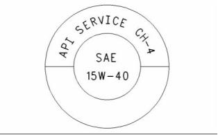
SEBU8121
41
Maintenance Section
Refill Capacities
DHD-1 oils are recommended for use in extended oil
change interval programs that optimize the life of the
oil. These oil change interval programs are based
on oil analysis. DHD-1 oils are recommended for
conditions that demand a premium oil. Your Perkins
dealer or your Perkins distributor has the specific
guidelines for optimizing oil change intervals.
NOTICE
Failure to follow these oil recommendations can cause
shortened engine service life due to deposits and/or
excessive wear.
Total Base Number (TBN) and Fuel Sulfur
Levels for Direct Injection (DI) Diesel
Engines
API CH-4 – API CH-4 oils were developed in order to
meet the requirements of the new high performance
diesel engines. Also, the oil was designed to
meet the requirements of the low emissions diesel
engines. API CH-4 oils are also acceptable for use
in older diesel engines and in diesel engines that
use high sulfur diesel fuel. API CH-4 oils may be
used in Perkins engines that use API CG-4 and API
CF-4 oils. API CH-4 oils will generally exceed the
performance of API CG-4 oils in the following criteria:
deposits on pistons, control of oil consumption, wear
of piston rings, valve train wear, viscosity control,
and corrosion.
The Total Base Number (TBN) for an oil depends on
the fuel sulfur level. For direct injection engines that
use distillate fuel, the minimum TBN of the new oil
must be 10 times the fuel sulfur level. The TBN is
defined by “ASTM D2896”. The minimum TBN of the
oil is 5 regardless of fuel sulfur level. Illustration 19
demonstrates the TBN.
Three new engine tests were developed for the API
CH-4 oil. The first test specifically evaluates deposits
on pistons for engines with the two-piece steel piston.
This test (piston deposit) also measures the control
of oil consumption. A second test is conducted
with moderate oil soot. The second test measures
the following criteria: wear of piston rings, wear of
cylinder liners, and resistance to corrosion. A third
new test measures the following characteristics with
high levels of soot in the oil: wear of the valve train,
resistance of the oil in plugging the oil filter, and
control of sludge.
g00799818
Illustration 19
(Y) TBN by “ASTM D2896”
In addition to the new tests, API CH-4 oils have
tougher limits for viscosity control in applications that
generate high soot. The oils also have improved
oxidation resistance. API CH-4 oils must pass an
additional test (piston deposit) for engines that use
aluminum pistons (single piece). Oil performance is
also established for engines that operate in areas
with high sulfur diesel fuel.
(X) Percentage of fuel sulfur by weight
(1) TBN of new oil
(2) Change the oil when the TBN deteriorates to 50 percent of
the original TBN.
Use the following guidelines for fuel sulfur levels that
exceed 1.5 percent:
• Choose an oil with the highest TBN that meets one
of these classifications: EMA DHD-1 and API CH-4.
All of these improvements allow the API CH-4
oil to achieve optimum oil change intervals. API
CH-4 oils are recommended for use in extended oil
change intervals. API CH-4 oils are recommended
for conditions that demand a premium oil. Your
Perkins dealer or your Perkins distributor has specific
guidelines for optimizing oil change intervals.
• Reduce the oil change interval. Base the oil
change interval on the oil analysis. Ensure that the
oil analysis includes the condition of the oil and
a wear metal analysis.
Excessive piston deposits can be produced by an oil
with a high TBN. These deposits can lead to a loss
of control of the oil consumption and to the polishing
of the cylinder bore.
Some commercial oils that meet the API
classifications may require reduced oil change
intervals. To determine the oil change interval, closely
monitor the condition of the oil and perform a wear
metal analysis.
NOTICE
Operating Direct Injection (DI) diesel engines with fuel
sulphur levels over 0.5 percent will require shortened
oil change intervals in order to help maintain adequate
wear protection.
This document has been printed from SPI². Not for Resale
![]()
![]()
![]()
![]()
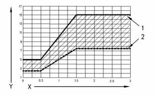
![]()
![]()
![]()
42
SEBU8121
Maintenance Section
Refill Capacities
Table 6
Some synthetic base oils have performance
characteristics that enhance the service life of the
oil. Perkins does not recommend the automatic
extending of the oil change intervals for any type of
oil.
Percentage of Sulfur in
the fuel
Oil change interval
Lower than 0.5
0.5 to 1.0
Normal
0.75 of normal
0.50 of normal
Re-refined base stock oil
Greater than 1.0
Re-refined base stock oil are acceptable for use in
Perkins engines if these oils meet the performance
requirements that are specified by Perkins.Re-refined
base stock oil can be used exclusively in finished oil
or in a combination with new base stock oil . The US
military specifications and the specifications of other
heavy equipment manufacturers also allow the use of
re-refined base stock oil that meet the same criteria.
Lubricant Viscosity Recommendations
for Direct Injection (DI) Diesel Engines
The correct SAE viscosity grade of oil is determined
by the minimum ambient temperature during
cold engine start-up, and the maximum ambient
temperature during engine operation.
The process that is used to make re-refined base
stock oil should adequately remove all wear metals
that are in the used oil and all the additives that
are in the used oil. The process that is used to
make re-refined base stock oil generally involves the
process of vacuum distillation and hydrotreating the
used oil. Filtering is adequate for the production of
high quality, re-refined base stock oil.
Refer to Table 7 (minimum temperature) in order to
determine the required oil viscosity for starting a cold
engine.
Refer to Table 7 (maximum temperature) in order to
select the oil viscosity for engine operation at the
highest ambient temperature that is anticipated.
Generally, use the highest oil viscosity that is
available to meet the requirement for the temperature
at start-up.
Lubricants for Cold Weather
When an engine is started and an engine is operated
in ambient temperatures below −20 °C (−4 °F), use
multigrade oils that are capable of flowing in low
temperatures.
Table 7
Engine Oil Viscosity
EMA LRG-1
API CH-4
Ambient Temperature
These oils have lubricant viscosity grades of SAE
0W or SAE 5W.
Minimum
Maximum
Viscosity Grade
SAE 0W20
SAE 0W30
SAE 0W40
SAE 5W30
SAE 5W40
SAE 10W30
SAE 15W40
−40 °C (−40 °F)
−40 °C (−40 °F)
−40 °C (−40 °F)
−30 °C (−22 °F)
−30 °C (−22 °F)
−20 °C (−4 °F)
−10 °C (14 °F)
10 °C (50 °F)
30 °C (86 °F)
40 °C (104 °F)
30 °C (86 °F)
40 °C (104 °F)
40 °C (104 °F)
50 °C (122 °F)
When an engine is started and operated in ambient
temperatures below 30 °C ( 22 °F), use a synthetic
−
−
base stock multigrade oil with an 0W viscosity grade
or with a 5W viscosity grade. Use an oil with a pour
point that is lower than −50 °C (−58 °F).
The number of acceptable lubricants is limited in
cold weather conditions. Perkins recommends the
following lubricants for use in cold weather conditions:
First Choice – Use oil with an EMA DHD-1
Recommended Guideline. Use a CH-4 oil that has
an API license. The oil should be either SAE 0W20,
SAE 0W30, SAE 0W40, SAE 5W30, or SAE 5W40
lubricant viscosity grade.
Synthetic Base Stock Oil
Synthetic base oils are acceptable for use in
these engines if these oils meet the performance
requirements that are specified for the engine.
Second Choice – Use an oil that has a CH-4
additive package. Although the oil has not been
tested for the requirements of the API license, the oil
must be either SAE 0W20, SAE 0W30, SAE 0W40,
SAE 5W30, or SAE 5W40.
Synthetic base oils generally perform better than
conventional oils in the following two areas:
• Synthetic base oils have improved flow at low
temperatures especially in arctic conditions.
• Synthetic base oils have improved oxidation
stability especially at high operating temperatures.
This document has been printed from SPI². Not for Resale
![]()


SEBU8121
43
Maintenance Section
Refill Capacities
• The Wear Rate Analysis monitors the wear of the
engine’s metals. The amount of wear metal and
type of wear metal that is in the oil is analyzed. The
increase in the rate of engine wear metal in the
oil is as important as the quantity of engine wear
metal in the oil.
NOTICE
Shortened engine service life could result if second
choice oils are used.
Aftermarket Oil Additives
• Tests are conducted in order to detect
Perkins does not recommend the use of aftermarket
additives in oil. It is not necessary to use aftermarket
additives in order to achieve the engine’s maximum
service life or rated performance. Fully formulated,
finished oils consist of base oils and of commercial
additive packages. These additive packages are
blended into the base oils at precise percentages in
order to help provide finished oils with performance
characteristics that meet industry standards.
contamination of the oil by water, glycol or fuel.
• The Oil Condition Analysis determines the loss of
the oil’s lubricating properties. An infrared analysis
is used to compare the properties of new oil to the
properties of the used oil sample. This analysis
allows technicians to determine the amount of
deterioration of the oil during use. This analysis
also allows technicians to verify the performance
of the oil according to the specification during the
entire oil change interval.
There are no industry standard tests that evaluate
the performance or the compatibility of aftermarket
additives in finished oil. Aftermarket additives may
not be compatible with the finished oil’s additive
package, which could lower the performance of the
finished oil. The aftermarket additive could fail to
mix with the finished oil. This could produce sludge
in the crankcase. Perkins discourages the use of
aftermarket additives in finished oils.
Fuel Specifications
Fuel Recommendations
To get the correct power and performance from
the engine, use a fuel of the correct quality. The
recommended fuel specification for Perkins engines
is shown below:
To achieve the best performance from a Perkins
engine, conform to the following guidelines:
• Cetane number___________________________45 minimum
• Viscosity___________2,0 to 4.5 cSt at 40 °C (104 °F)
• Density________________________0.835 to 0.855 Kg/liter
• Sulfur_______________________0.2% of mass, maximum
• Distillation___________________85% at 350 °C (662 °F)
• Select the correct oil, or a commercial oil that meets
the “EMA Recommended Guideline on Diesel
Engine Oil” or the recommended API classification.
• See the appropriate “Lubricant Viscosities” table in
order to find the correct oil viscosity grade for your
engine.
• At the specified interval, service the engine. Use
new oil and install a , new oil filter.
• Lubricity
______________________________
460 micrometers
maximum wear scar on “ISO 12156 - 1”
Cetane number
• Perform maintenance at the intervals that are
specified in the Operation and Maintenance
Manual, “Maintenance Interval Schedule”.
This indicates the properties of ignition of the fuel.
Fuel with a low cetane number can be the root
cause of problems during cold start. This will affect
combustion.
S·O·S Oil analysis
Some engines may be equipped with an oil sampling
valve. If S·O·S oil analysis is required the oil sampling
valve is used to obtain samples of the engine oil. The
S·O·S oil analysis will complement the preventive
maintenance program.
Viscosity
This is the resistance to flow of a fluid. If this
resistance is outside the limits, the engine and the
engine starting performance in particular can be
affected.
The S·O·S oil analysis is a diagnostic tool that is used
to determine oil performance and component wear
rates. Contamination can be identified and measured
through the use of the S·O·S oil analysis. The S·O·S
oil analysis includes the following tests:
Sulfur
This document has been printed from SPI². Not for Resale
![]()
![]()
![]()
44
SEBU8121
Maintenance Section
Refill Capacities
High sulfur content of the fuel is not normally found
in Europe, North America or Australasia. This can
cause engine wear. When only high sulfur fuels
are available, it will be necessary that high alkaline
lubricating oil is used in the engine or that the
lubricating oil change interval is reduced.
“ASTM D975 - 91 Class 1D”
“JP7, Mil T38219”
“NATO F63”
NOTICE
Distillation
These fuels should have a wear scar value of 650
micrometers maximum *HFRR to ISO 12156 - 1.*
This is an indication of the mixture of different
hydrocarbons in the fuel. A high ratio of light weight
hydrocarbons can affect the characteristics of
combustion.
Group 3 (aviation kerosene fuels): Specification
These fuels need additives to achieve lubricity of 650
micrometers wear scar and the reliability of the fuel
injection pump will be reduced. The fuel injection
pump is not covered by a warranty, even when the
additives are included.
Lubricity
This is the capability of the fuel to prevent pump wear.
Diesel engines have the ability to burn a wide variety
of fuels. These fuels are divided into four general
groups:
“JP5 MIL T5624 (Avcat FSII, NATO F44”
“JP8 T83133 (Avtur FSII, NATO F34”
“Jet A”
• Group 1 (preferred fuels)
• Group 2 (permissible fuels)
• Group 3 (aviation kerosene fuels)
• Other fuels
“Jet A1, NATO F35, XF63”
Low temperature fuels
Special fuels for use in cold weather may be available
for engine operation at temperatures below 0 °C
(32 °F). These fuels limit the formation of wax in the
fuel oil at low temperatures. If wax forms in the fuel
oil, this could stop the flow of fuel oil through the filter.
Group 1 (preferred fuels): Specification
“DERV to EN590”
Note: Only use Arctic fuels when the temperature is
below 0 °C (32 °F). Do not use Arctic fuels when the
ambient temperature is above 0 °C (32 °F). To ensure
that the time period between cranking the engine and
first fire is kept to a minimum, only use fuel of the
correct viscosity and at the correct temperature.
Note: These fuels that lack lubricity may cause the
following problems:
• Low engine power
• Difficult starting in hot conditions or in cold
conditions
Gas oil to “BS2869 Class A2”
• White smoke
“ASTM D975 - 91 Class 2D” This can only be used if
the fuel has the correct specification of lubricity.
• Deterioration of emissions and misfire at certain
operating conditions
“JIS K2204 (1992) Grades 1,2,3 and Special Grade
3” This can only be used if the fuel has the correct
specification of lubricity.
Biofuel: Specification
Biofuel: A 5% mix of RME to EN14214 in conventional
fuel is permitted.
Note: If low sulfur or low sulfur aromatic fuels are
used, then fuel additives can be used to increase
lubricity.
NOTICE
Group 2 (permissible fuels): Specification
Water emulsion fuels: These fuels are not permitted
These fuel specifications are considered acceptable
for issues of warranty. However,these fuels may
reduce the life of the engine, the engine’s maximum
power and the engine’s fuel efficiency.
Refer to the following fuel specifications for
North America.
This document has been printed from SPI². Not for Resale
![]()
![]()
![]()
![]()
![]()
SEBU8121
45
Maintenance Section
Refill Capacities
The preferred fuels provide maximum engine service
life and performance. The preferred fuels are distillate
fuels. These fuels are commonly called diesel fuel
or gas oil.
(Table 8, contd)
Copper Strip
Corrosion
No. 3 maximum
“D130”
“D86”
10% at 282 °C
(540 °F)
The permissible fuels are crude oils or blended fuels.
Use of these fuels can result in higher maintenance
costs and in reduced engine service life.
maximum
Distillation
90% at 360 °C
(680 °F)
Diesel fuels that meet the specifications in Table
8 will help to provide maximum engine service life
and performance. In North America, diesel fuel that
is identified as No. 2-D in “ASTM D975” generally
meets the specifications. Table 8 is for diesel fuels
that are distilled from crude oil. Diesel fuels from
other sources could exhibit detrimental properties
that are not defined or controlled by this specification.
maximum
Flash Point
API Gravity
legal limit
“D93”
30 minimum
45 maximum
“D287”
6 °C (10 °F)
minimum
Pour Point
“D97”
below ambient
temperature
Table 8
Perkins Specifications for Distillate Diesel Fuel
0.2% maximum
“D3605”
or
Sulfur
(1)
Specifications
Requirements
ASTM Test
“D1552”
Aromatics
35% maximum
“D1319”
2.0 cSt minimum
and 4.5 cSt
Kinematic
Viscosity
0.02% maximum
(weight)
“D445”
Ash
“D482”
“D524”
maximum at
(2)
40 °C (104 °F)
Carbon Residue
on 10% Bottoms
0.35% maximum
(weight)
Water and
Sediment
0.1% maximum
“D1796”
“D1744”
“D473”
40 minimum (DI
engines)
Cetane Number
“D613”
Water
0.1% maximum
0.05% maximum
(weight)
Sediment
The cloud
point must not
exceed the
lowest expected
ambient
Gum and Resins 10 mg per 100
Cloud Point
-
“D381”
(3)
mL maximum
0.38 mm
temperature.
(0.015 inch)
maximum at
25 °C (77 °F)
Lubricity
(4)
“D6079”
(continued)
(1) Perkins fuel systems and engine components can operate
on high sulfur fuels. Fuel sulfur levels affect exhaust
emissions. High sulfur fuels also increase the potential
for corrosion of internal components. Fuel sulfur levels
above 0.5 percent may significantly shorten the oil change
interval. For additional information, see this publication, “Fluid
Recommendations/Engine Oil” topic (Maintenance Section).
(2) The values of the fuel viscosity are the values as the fuel
is delivered to the fuel injection pumps. If a fuel with a low
viscosity is used, cooling of the fuel may be required to
maintain a 1.4 cSt viscosity at the fuel injection pump. Fuels
with a high viscosity might require fuel heaters in order to bring
down the viscosity to a 20 cSt viscosity.
(3) Follow the test conditions and procedures for gasoline (motor).
(4) The lubricity of a fuel is a concern with low sulfur fuel. To
determine the lubricity of the fuel, use either the “ASTM D6078
Scuffing Load Wear Test (SBOCLE)” or the “ASTM D6079 High
Frequency Reciprocating Rig (HFRR)” test. If the lubricity of a
fuel does not meet the minimum requirements, consult your
fuel supplier. Do not treat the fuel without consulting the fuel
supplier. Some additives are not compatible. These additives
can cause problems in the fuel system.
This document has been printed from SPI². Not for Resale
![]()


46
SEBU8121
Maintenance Section
Refill Capacities
Cooling System Specifications
NOTICE
Operating with fuels that do not meet the Perkins rec-
ommendations can cause the following effects: Start-
ing difficulty, poor combustion, deposits in the fuel in-
jectors, reduced service life of the fuel system, de-
posits in the combustion chamber, and reduced ser-
vice life of the engine.
General Coolant Information
NOTICE
Never add coolant to an overheated engine. Engine
damage could result. Allow the engine to cool first.
NOTICE
NOTICE
If the engine is to be stored in, or shipped to an area
with below freezing temperatures, the cooling system
must be either protected to the lowest outside temper-
ature or drained completely to prevent damage.
Heavy Fuel Oil (HFO), Residual fuel, or Blended fuel
must NOT be used in Perkins diesel engines. Severe
component wear and component failures will result if
HFO type fuels are used in engines that are configured
to use distillate fuel.
NOTICE
Frequently check the specific gravity of the coolant for
proper freeze protection or for anti-boil protection.
In extreme cold ambient conditions, you may use the
distillate fuels that are specified in Table 9. However,
the fuel that is selected must meet the requirements
that are specified in Table 8. These fuels are intended
to be used in operating temperatures that are down
to −54 °C (−65 °F).
Clean the cooling system for the following reasons:
• Contamination of the cooling system
• Overheating of the engine
Table 9
Distillate Fuels
(1)
• Foaming of the coolant
Specification
“MIL-T-5624R”
“ASTM D1655”
“MIL-T-83133D”
Grade
JP-5
NOTICE
Jet-A-1
JP-8
Never operate an engine without water temperature
regulators in the cooling system. Water temperature
regulators help to maintain the engine coolant at the
proper operating temperature. Cooling system prob-
lems can develop without water temperature regula-
tors.
(1) The fuels that are listed in this Table may not meet the
requirements that are specified in the “Perkins Specifications
for Distillate Diesel Fuel” Table. Consult the supplier for the
recommended additives in order to maintain the correct fuel
lubricity.
Many engine failures are related to the cooling
system. The following problems are related to cooling
system failures: Overheating, leakage of the water
pump, and plugged radiators or heat exchangers.
These fuels are lighter than the No. 2 grades of fuel.
The cetane number of the fuels in Table 9 must be
at least 40. If the viscosity is below 1.4 cSt at 38 °C
(100 °F), use the fuel only in temperatures below
0 °C (32 °F). Do not use any fuels with a viscosity
of less than 1.2 cSt at 38 °C (100 °F). Fuel cooling
may be required in order to maintain the minimum
viscosity of 1.4 cSt at the fuel injection pump.
These failures can be avoided with correct cooling
system maintenance. Cooling system maintenance is
as important as maintenance of the fuel system and
the lubrication system. Quality of the coolant is as
important as the quality of the fuel and the lubricating
oil.
There are many other diesel fuel specifications that
are published by governments and by technological
societies. Usually, those specifications do not
review all the requirements that are addressed
in this specification. To ensure optimum engine
performance, a complete fuel analysis should be
obtained before engine operation. The fuel analysis
should include all of the properties that are listed in
Table 8.
Coolant is normally composed of three elements:
Water, additives, and glycol.
Water
Water is used in the cooling system in order to
transfer heat.
Distilled water or deionized water is
recommended for use in engine cooling systems.
This document has been printed from SPI². Not for Resale
![]()
![]()
![]()
![]()
![]()
![]()
![]()
![]()
![]()
![]()
![]()
![]()
![]()
SEBU8121
47
Maintenance Section
Refill Capacities
DO NOT use the following types of water in cooling
systems: Hard water, softened water that has been
conditioned with salt, and sea water.
• Plugging of radiators, coolers, and small passages
Glycol
If distilled water or deionized water is not available,
use water with the properties that are listed in Table
10.
Glycol in the coolant helps to provide protection
against the following conditions:
• Boiling
Table 10
Perkins Minimum Acceptable Water Requirements
• Freezing
Property
Maximum Limit
40 mg/L
• Cavitation of the water pump
Chloride (Cl)
For optimum performance, Perkins recommends a
1:1 mixture of a water/glycol solution.
Sulfate (SO4)
Total Hardness
Total Solids
Acidity
100 mg/L
170 mg/L
Note: Use a mixture that will provide protection
340 mg/L
against the lowest ambient temperature.
pH of 5.5 to 9.0
Note: 100 percent pure glycol will freeze at a
temperature of −23 °C (−9 °F).
For a water analysis, consult one of the following
sources:
Most conventional coolant/antifreezes use ethylene
glycol. Propylene glycol may also be used. In a 1:1
mixture with water, ethylene and propylene glycol
provide similar protection against freezing and
boiling. See Tables 11 and 12.
• Local water utility company
• Agricultural agent
• Independent laboratory
Table 11
Ethylene Glycol
Additives
Freeze
Boil
Concentration
Additives help to protect the metal surfaces of
the cooling system. A lack of coolant additives or
insufficient amounts of additives enable the following
conditions to occur:
Protection
Protection
50 Percent
60 Percent
−36 °C (−33 °F) 106 °C (223 °F)
−
−51 °C ( 60 °F) 111 °C (232 °F)
• Corrosion
NOTICE
Do not use propylene glycol in concentrations that ex-
ceed 50 percent glycol because of propylene glycol’s
reduced heat transfer capability. Use ethylene glycol
in conditions that require additional protection against
boiling or freezing.
• Formation of mineral deposits
• Rust
• Scale
• Foaming of the coolant
Many additives are depleted during engine operation.
These additives must be replaced periodically.
Additives must be added at the correct concentration.
Overconcentration of additives can cause the
inhibitors to drop out-of-solution. The deposits can
enable the following problems to occur:
• Formation of gel compounds
• Reduction of heat transfer
• Leakage of the water pump seal
This document has been printed from SPI². Not for Resale
400-100-8969???15088860848
0574-26871589? 15267810868
0574-26886646? 15706865167
0574-26871569 18658287286


 Deutsch
 Espaol
 Franais
 Italiano
 Português
 日本
日本 韓國(guó)
 阿拉伯
阿拉伯 български
 hrvatski
 esky
esky Dansk
Dansk Nederlands
 suomi
suomi Ελληνικ
 印度
印度 norsk
norsk Polski
 Roman
Roman русский
 Svenska
 中文(簡(jiǎn))