
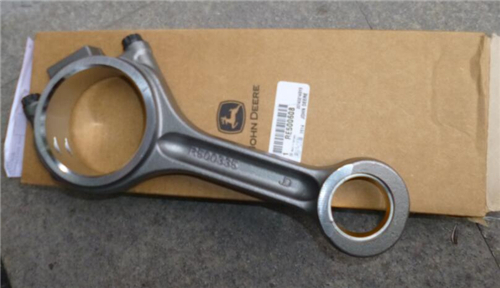
強(qiáng)鹿柴油機(jī)連桿的維修檢測與標(biāo)準(zhǔn)值參數(shù)
詳細(xì)描述
John Deere約翰迪爾強(qiáng)鹿柴油機(jī)連桿的檢測與標(biāo)準(zhǔn)值參數(shù)
1. Inspect rod bearings for damage or wear.
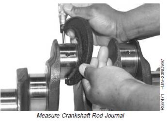
2. Measure crankshaft rod journal OD at several points.
Specification
Crankshaft Journal—OD 77.800—77.826 mm (3.0629—3.0640 in.)
3. Assemble connecting rod, cap, and bearings with OLD cap screws. Tighten cap screws to 58 N•m (43 lb-ft).n Tighten cap screws an additional 90—100°. (SeeTORQUE-TURN CONNECTING ROD CAP SCREWSlater in this group.)
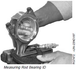
4. Measure assembled rod bearing ID.
Specification
Assembled Rod Bearing—ID 77.876—77.927 mm (3.0659—3.0679 in.)
5. Subtract crankshaft journal OD from rod bearing ID to determine oil clearance. Replace bearings if oilclearance is out specification.
Specification
Connecting Rod Bearing-to-Journal (New Parts)— Oil Clearance 0.050—0.127 mm (0.0020—0.0050 in.)
Wear Limit .............................................................. 0.152 mm (0.0060 in.)
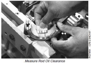
Inspect and Measure Connecting RodBearings (Rod and Crankshaft in Engine)
NOTE: Use PLASTIGAGEâ as directed by manufacturer.PLASTIGAGEâ will determine oil clearance, but will not indicate condition of either surface.
1. Remove rod cap. Place a piece of PLASTIGAGEâ in center of bearing. Install rod cap using OLD cap screws. Tighten cap screws to 58 N•m (43 lb-ft).
Tighten cap screw an additional 90—100°. (See TORQUE-TURN CONNECTING ROD CAP SCREWS later in this group.)
2. Remove rod cap. Compare width of PLASTIGAGEâ with scale provided on package to determine clearance. Replace bearings if oil clearance is out of specification.
Inspect Rod and Cap
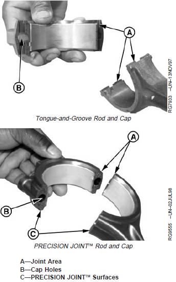
1. Inspect rod and cap for wear or damage, such as chips or nicks in the joint area (A).
IMPORTANT: Do not nick the joint surfaces of the rod and cap. This is very critical on PRECISION JOINTä rods to ensure proper seating. Never scrape these surfaces (C) with a wire brush or other tool. The interlocking mating surfaces must be preserved.
2. Inspect in and around cap screw holes (B) in cap. If any imperfections are found, replace rod and cap.
3. Carefully clamp rod in a soft-jawed vise (cap end upward).
IMPORTANT: Never use new connecting rod cap screws when checking rod bore ID. Use new cap screws only for final assembly of connecting rods.
4. Install cap WITHOUT bearing inserts. Use old cap screws.
5. Tighten cap screws to 58 N•m (43 lb-ft). Turn cap screws an additional 90—100°. See TORQUE-TURN CONNECTING ROD CAP SCREWS later in this group.
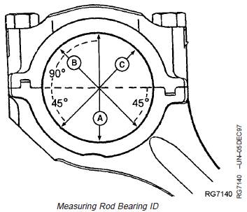
6. Using an inside micrometer, measure rod bore at center of bore and record measurements as follows:
· At right angle to rod-to-cap joint (A).
· At 45 degrees left of measurement step “A” (B).
· At 45 degrees right of measurement step “A” (C).
7. Compare measurements to specifications.
Specification
Connecting Rod Bore (WithoutBearing Inserts)—ID 82.677—82.703 mm (3.2550—3.2560 in.)
8. If difference between the greatest and least measurement exceeds out-of-round specification, replace connecting rod.
Specification
Connecting Rod Bore—Maximum
Permissible Out-of-Round ...................................... 0.038 mm (0.0015 in.)
John Deere約翰迪爾強(qiáng)鹿柴油機(jī)活塞銷與連桿襯套的檢查與標(biāo)準(zhǔn)值參數(shù)
1. Visually inspect piston pin. Pin must be in good condition with no visible wear.
IMPORTANT: Do not attempt to polish or refinish piston pin. Pin has a highly polished surface.
2. Dip piston pin in clean engine oil.
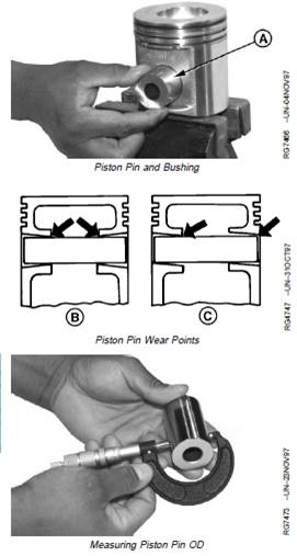
3. Install pin (A) through piston. Pin should pass through piston using only light thumb pressure.
4. Insert pin from both sides. If pin enters freely, but binds in the center, the bore could be tapered (B).
5. Insert pin to check for bore alignment (C). Pin should not “click” or need to be forced into bore on opposite side.
6. Measure piston pin OD. Replace if not within specification.
Specification
Piston Pin (Small)—OD 34.920—34.930 mm (1.3748—1.3752 in.)
Wear Limit ............................................................ 34.907 mm (1.3743 in.)
Piston Pin (Large)—OD 41.270—41.280 mm (1.6248—1.6252 in.)
Wear Limit ............................................................ 41.257 mm (1.6243 in.)
Piston Pin—Length 71.51—72.11 mm (2.815—2.839 in.)
A—Piston Pin
B—Tapered Bore
C—Bore Alignment
NOTE: Straight-end rods have an oil hole; tapered-end rods do not.
7. Lubrication hole must be open.
8. Measure pin bushing ID and compare to pin OD to determine oil clearance.
Specification
Piston Pin Bushing Installed (Small Pin)—ID 34.950—34.976 mm (1.3760—1.3770 in.)
Wear Limit ............................................................ 35.026 mm (1.3790 in.)
Piston Pin Bushing Installed (Large Pin)—ID 41.300—41.326 mm (1.6260—1.6270 in.)
Wear Limit ............................................................ 41.376 mm (1.6290 in.)
Piston Pin-to-Bushing—Oil Clearance 0.020—0.056 mm (0.0008—0.0022 in.)
Wear Limit .............................................................. 0.102 mm (0.0040 in.)
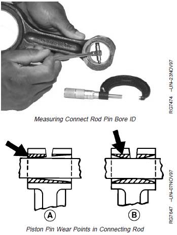
9. Insert pin from either side of rod bushing. If pin is free on one end, but tight on the other, the bore could be tapered (A). If pin enters freely from both sides, but is tight in the center, bore is bell mouthed (B).
A—Tapered Bore
B—Bell Mouthed Bore
連桿襯套的拆卸方法與標(biāo)準(zhǔn)值參數(shù)
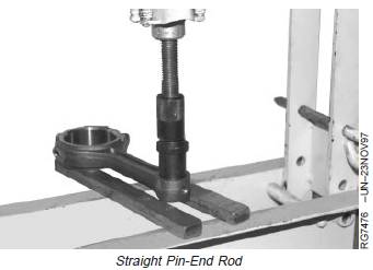
Removing Piston Pin Bushing on Straight Pin-End Rod
Use JD286 (JD-286) Piston Pin Bushing Remover and Installer for 41 mm (1.6 in.) pin, or JDE88 Piston Pin Bushing Remover and Installer for 35 mm (1.3 in.) pin to remove bushing.
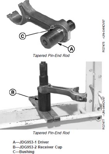
Removing Piston Pin Bushing on Tapered Pin-End Rod
1. Select JDG953-1 Driver (A) and JDG953-2 ReceiverCup (B) from JDG953 Connecting Rod Bushing Service Set to remove bushing (C) from tapered rod.
2. Slide driver into one side of rod bushing. Turn driverbuntil taper on driver flange matches up with taper on the bushing.
3. Install receiver cup onto opposite side of rod bushing. NOTE: Stud in cup keeps rod properly located on the cup.
IMPORTANT: If bushing is heavily worn, the driver may contact the ID of the rod bore. Be careful not to damage the rod bore.
4. Using hydraulic press, press bushing out of the rod until driver and bushing fall into receiver cup.
5. Clean, inspect, and measure ID of rod pin bore, as described later in this group.
John Deere約翰迪爾強(qiáng)鹿柴油機(jī)連桿中的活塞銷襯套的安裝技巧與標(biāo)準(zhǔn)值參數(shù)
Carefully file a slight chamfer on edge of rod pin bore.Remove any burrs or sharp edges from edge of bushingbore.
NOTE: Tapered pin-end rods do not have a lubricationhole in the rod or bushing.
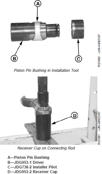
Installing Piston Pin Bushing in Tapered Pin-End Rod
NOTE: JDG953-1, JDG953-2 and JDG738-2 arecontained in JDG953 Connecting Rod BushingService Set.
1. Slide bushing (A) onto JDG953-1 Driver (B) and install JDG738-2 Installer Pilot (C) onto O-ring end of driver.Apply clean engine oil or grease to OD of newbushing, OD of pilot ring, and ID of rod pin bore.. Insert driver into rod pin bore so pilot ring pilots in rod bore, and bushing taper aligns with taper on driverflange.
3. Install JDG953-2 Receiver Cup (D) onto the oppositeside of rod.
4. Press bushing into rod bore until edge of bushing is flush or just slightly below rod face.
5. If necessary, have the new bushing reamed by a specialized machine shop to obtain specified oil clearance with piston pin.
Specification
Connecting Rod Pin-to-Bushing (Tapered Pin-End)—Oil Clearance 0.020—0.056 mm (0.0008—0.0022 in.)
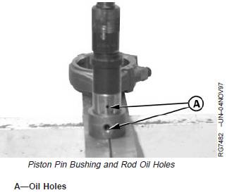
Installing Piston Pin Bushing in Straight Pin-End Rod
IMPORTANT: Oil holes (A) MUST be aligned. If holes are not aligned, remove and discard bushing. Install a new bushing. DO NOT attempt to reuse the bushing. Install bushing in rod.
1. Use JD286 (JD-286) Piston Pin Bushing Remover and Installer for 41 mm (1.6 in.) pin or JDE88 Piston Pin Bushing Remover and Installer for 35 mm (1.3 in.) pin to install bushing.
2. Press bushing into rod bore until edge of bushing is flush or just slightly below machined surface on face of rod.
3. Remove rod from press.
4. ID of new bushing must be precision bored by specialized machine shop to specifications.
Specification
Connecting Rod Pin-to-Bushing(Straight Pin-End)—Oil Clearance 0.020—0.056 mm (0.0008—0.0022 in.)
Wear Limit .............................................................. 0.102 mm (0.0040 in.)
連桿中心到連桿中心孔位置的測量與標(biāo)準(zhǔn)值參數(shù)
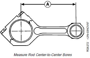
Measure rod center-to-center bores (A) (with bushingsremoved). Compare to specifications given below.Replace rod if necessary.
Specification
Rod Bearing Bore-to-Piston PinBushing Bore(Center-to-Center)—Measurement 202.95—203.05 mm(7.990—7.994 in.)
A—Center-to-Center Measurement
400-100-8969???15088860848
0574-26871589? 15267810868
0574-26886646? 15706865167
0574-26871569 18658287286


 Deutsch
 Espaol
 Franais
 Italiano
 Português
 日本
日本 韓國
韓國 阿拉伯
阿拉伯 български
 hrvatski
 esky
esky Dansk
Dansk Nederlands
 suomi
suomi Ελληνικ
 印度
印度 norsk
norsk Polski
 Roman
Roman русский
 Svenska
 中文(簡)
中文(簡)